User:Jcreer/New Arc Functions in SMS 13.2: Difference between revisions
| Line 21: | Line 21: | ||
*''Arc to trim/extend to'' – This option has a combo box of the two arc IDs. Select the arc that will be used as the source arc. | *''Arc to trim/extend to'' – This option has a combo box of the two arc IDs. Select the arc that will be used as the source arc. | ||
The tool | The ''Trim/Extend Arc'' tool determines the number of intersections between the two arcs. It uses the following principles to do this: | ||
* intersections | * The number of intersections will indicate to the tool to use the "Extend" operation. This will do the following: | ||
*Find the end point of arc 1 that is closest to arc 2. This is the point that will be moved | *Find the end point of arc 1 that is closest to arc 2. This is the point that will be moved. | ||
*Extend the ending segment of the arc including the point to be moved to see if it intersects the trimming arc (arc 2) | *Extend the ending segment of the arc including the point to be moved to see if it intersects the trimming arc (arc 2). The tool will check to see if this operation can be done act as follows: | ||
**If yes | **If yes the tool will move the point that is being moved to the intersection. | ||
**If no | **If no the tool will see if the last segment extended intersects either of the rays extending from the end of the trimming arc and do the following: | ||
***If intersects both | ***If intersects both then the tool will move the point that is being moved to the nearest intersection. | ||
***If intersects one | ***If intersects one the the tool will move the point that is being moved to the intersection. | ||
***If intersects none | ***If intersects none the the will will display an error saying it can’t extend the arc. | ||
*1 or more intersections indicate a “Trim” operation | *1 or more intersections indicate a “Trim” operation | ||
**Insert a node into the first arc at the first intersection | **Insert a node into the first arc at the first intersection | ||
Revision as of 16:21, 13 October 2021
There have been repeated requests from users at training courses of SMS to add a few CAD like operations to SMS. The comments have been strong enough to imply that if we add these few operations the users will not need to use CAD at all (but I don’t believe that).
The operations are:
Specify Arc Length
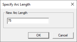
The Specify Arc Length tool can be used to create a new node/vertex a specified distance down the length of an arc. It is accessed by selecting an arc then right-clicking and selecting the Specify arc length command. In the Specify Arc Length dialog, there is the following option:
- New Arc Length – Enter the desired arc length. The units for this length is either feet or meters based on projection.
- If specified length is less than arc length, a new node is added to the arc at the specified distance along the arc.
- If the distance specified is greater than the length of the arc, the end node of the arc is extended to make the arc length the specified distance.
Notes:
- This can change the shape of any arc attached to the end of the selected arc.
- This tool only operates on the arc in the defined arc direction.
Trim/Extend Arc
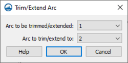
SMS can either trim or extend an arc to match the length of another arc. This is done by selecting two arcs then right-clicking and selecting the Trim/Extend Arc command. This command appears if two and only two arcs are selected. The Trim/Extend Arc dialog has the following options:
- Arc to be trimmed/extended – This option has a combo box of the two arc IDs. Select the arc that will be modified.
- Arc to trim/extend to – This option has a combo box of the two arc IDs. Select the arc that will be used as the source arc.
The Trim/Extend Arc tool determines the number of intersections between the two arcs. It uses the following principles to do this:
- The number of intersections will indicate to the tool to use the "Extend" operation. This will do the following:
- Find the end point of arc 1 that is closest to arc 2. This is the point that will be moved.
- Extend the ending segment of the arc including the point to be moved to see if it intersects the trimming arc (arc 2). The tool will check to see if this operation can be done act as follows:
- If yes the tool will move the point that is being moved to the intersection.
- If no the tool will see if the last segment extended intersects either of the rays extending from the end of the trimming arc and do the following:
- If intersects both then the tool will move the point that is being moved to the nearest intersection.
- If intersects one the the tool will move the point that is being moved to the intersection.
- If intersects none the the will will display an error saying it can’t extend the arc.
- 1 or more intersections indicate a “Trim” operation
- Insert a node into the first arc at the first intersection
- Delete the first portion of the newly split arc
Create Horizontal or Vertical Segment
Create horizontal or vertical segments when digitizing an arc.
- While digitizing an arc user can hold down a key (h or v). If “h” is held down, the next point on the arc will be at the same Y value as the previous point. If the “v” is held down the next point on the arc will be at the same X value. (This could work like when we are creating the second direction of a grid frame.)
Offset an arc graphically
- User selects an arc and holds down the mouse button (dragging). The button down (world location is saved) (Note: we may want to have a “lock arcs” option that works similar to the lock nodes feature does now to prevent accidental dragging. We wouldn’t do this right now.)
- On button up, the button up world location is saved.
- The translation vector is computed as ButtonUpLoc - ButtonDownLoc.
- All nodes/vertices of the selected arc are translated by the translation vector.
- Note: this also impacts the arcs attached to the end points of the arc being dragged.

