SMS:WAM Spectra from STWAVE Grids: Difference between revisions
| (14 intermediate revisions by the same user not shown) | |||
| Line 4: | Line 4: | ||
Spectra sites can be made at any ocean cell on a Cartesian grid. To make a spectra site, select a cell on the desired Cartesian grid and change the cell attribute to Spectra Site and give it a name. If more than one cell is selected, then the name the spectra sites will receive is the name given concatenated with a number. | Spectra sites can be made at any ocean cell on a Cartesian grid. To make a spectra site, select a cell on the desired Cartesian grid and change the cell attribute to Spectra Site and give it a name. If more than one cell is selected, then the name the spectra sites will receive is the name given concatenated with a number. | ||
After WAM has run, and the spectra files have been read back into SMS, the spectral energy graph of the spectra sites may be viewed by right-clicking on the selected cell where the site is and selecting Spectral Energy. The spectra files may be read back into SMS by selecting the grid, and choosing Read Spectral Files from the WAM menu. The spectra files should be within the grid's folder within the simulation folder. | After WAM has run, and the spectra files have been read back into SMS, the spectral energy graph of the spectra sites may be viewed by right-clicking on the selected cell where the site is and selecting '''Spectral Energy'''. The spectra files may be read back into SMS by selecting the grid, and choosing '''Read Spectral Files''' from the ''WAM'' menu. The spectra files should be within the grid's folder within the simulation folder. | ||
==WAM Spectra From STWAVE Grids== | ==WAM Spectra From STWAVE Grids== | ||
WAM can be used to provide boundary condition information to a spectral wave model such as STWAVE. WAM | [[File:WAMtoSTWAVEoptions.png|thumb|275 px|The ''WAM to STWAVE Options'' dialog will show all available STWAVE grids]] | ||
[[File:WAM SpectralSitesFromSTWAVE.png|thumb|300 px|The ''WAM Spectral Sites from STWAVE'' dialog]] | |||
WAM can be used to provide boundary condition information to a spectral wave model such as STWAVE. '''WAM→STWAVE''' has a defined and support mechanism for converting WAM spectral output into STWAVE input. | |||
The first part of this process is to define the locations where WAM will generate output for the STWAVE BC. Two or more WAM cells may be used along a STWAVE boundary. The STWAVE grids must exist and the boundaries types specified (which side(s) to apply spectra. | The first part of this process is to define the locations where WAM will generate output for the STWAVE BC. Two or more WAM cells may be used along a STWAVE boundary. The STWAVE grids must exist and the boundaries types specified (which side(s) to apply spectra. | ||
To create spectral sites along the STWAVE boundaries: | To create spectral sites along the STWAVE boundaries: | ||
# Verify/Modify the boundary types of a STWAVE Grid.<p><ol style="list-style-type: lower-alpha;"><li>Select a STWAVE grid.</li><li>Select menu item | # Verify/Modify the boundary types of a STWAVE Grid.<p><ol style="list-style-type: lower-alpha;"><li>Select a STWAVE grid.</li><li>Select menu item '''STWAVE''' → '''Model Control''' then press the '''Boundary Condition...''' button.</li><li>Select the appropriate boundary type for each edge.</li><li>Repeat for each STWAVE grid.</li></ol></p> | ||
# Select and right-click on a WAM grid from the tree item on the left of SMS. | # Select and right-click on a WAM grid from the tree item on the left of SMS. | ||
#Select | #Select '''Create spectral sites...''' to bring up the ''WAM spectral spectral sites from STWAVE'' dialog. | ||
#Select the grids | #Select the grids the project should to generate sites for. | ||
#Select a spacing option on the right hand side and the number of points/sites. | #Select a spacing option on the right hand side and the number of points/sites. | ||
#Press | #Press '''Ok'''. | ||
Each STWAVE boundary cell will have a candidate WAM corner (where WAM spectra are output). A candidate corner is the nearest WAM corner to that STWAVE boundary cell. Multiple STWAVE cells may have the same candidate WAM corner. Duplicate WAM corners are automatically removed. | Each STWAVE boundary cell will have a candidate WAM corner (where WAM spectra are output). A candidate corner is the nearest WAM corner to that STWAVE boundary cell. Multiple STWAVE cells may have the same candidate WAM corner. Duplicate WAM corners are automatically removed. | ||
| Line 27: | Line 29: | ||
*Spacing by every 2 candidate points will keep every other corner and make those spectra sites. | *Spacing by every 2 candidate points will keep every other corner and make those spectra sites. | ||
Regardless of the option selected at least two corners will be used on each STAVE boundary. | Regardless of the option selected at least two corners will be used on each STAVE boundary. | ||
==Related Topics== | |||
* [[SMS:WAM|WAM]] | |||
{{Template:Navbox SMS}} | {{Template:Navbox SMS}} | ||
[[Category:WAM|S]] | |||
[[Category:Spectral Energy|W]] | |||
[[Category:Needs Update]] | |||
Latest revision as of 21:38, 10 June 2016
Spectra Sites
Since the spectra data of every cell of the grid at each timestep would take an unreasonable amount of disk space, WAM writes spectra data at user specified cells. These cells are referred to as spectra sites and can be specified within the SMS interface. The spectra output can also be visualized on these cells.
Spectra sites can be made at any ocean cell on a Cartesian grid. To make a spectra site, select a cell on the desired Cartesian grid and change the cell attribute to Spectra Site and give it a name. If more than one cell is selected, then the name the spectra sites will receive is the name given concatenated with a number.
After WAM has run, and the spectra files have been read back into SMS, the spectral energy graph of the spectra sites may be viewed by right-clicking on the selected cell where the site is and selecting Spectral Energy. The spectra files may be read back into SMS by selecting the grid, and choosing Read Spectral Files from the WAM menu. The spectra files should be within the grid's folder within the simulation folder.
WAM Spectra From STWAVE Grids
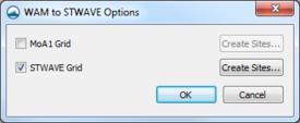
WAM can be used to provide boundary condition information to a spectral wave model such as STWAVE. WAM→STWAVE has a defined and support mechanism for converting WAM spectral output into STWAVE input.
The first part of this process is to define the locations where WAM will generate output for the STWAVE BC. Two or more WAM cells may be used along a STWAVE boundary. The STWAVE grids must exist and the boundaries types specified (which side(s) to apply spectra.
To create spectral sites along the STWAVE boundaries:
- Verify/Modify the boundary types of a STWAVE Grid.
- Select a STWAVE grid.
- Select menu item STWAVE → Model Control then press the Boundary Condition... button.
- Select the appropriate boundary type for each edge.
- Repeat for each STWAVE grid.
- Select and right-click on a WAM grid from the tree item on the left of SMS.
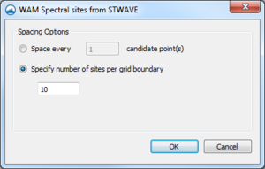
- Select Create spectral sites... to bring up the WAM spectral spectral sites from STWAVE dialog.
- Select the grids the project should to generate sites for.
- Select a spacing option on the right hand side and the number of points/sites.
- Press Ok.
Each STWAVE boundary cell will have a candidate WAM corner (where WAM spectra are output). A candidate corner is the nearest WAM corner to that STWAVE boundary cell. Multiple STWAVE cells may have the same candidate WAM corner. Duplicate WAM corners are automatically removed.
Spacing can be done by either spacing along candidate corners or by specifying an exact number of sites/corners along each boundary.
If spacing by candidate point(s) is chosen:
- Spacing by every 1 candidate points will keep all candidate corners and make them spectra sites.
- Spacing by every 2 candidate points will keep every other corner and make those spectra sites.
Regardless of the option selected at least two corners will be used on each STAVE boundary.
Related Topics
SMS – Surface-water Modeling System | ||
|---|---|---|
| Modules: | 1D Grid • Cartesian Grid • Curvilinear Grid • GIS • Map • Mesh • Particle • Quadtree • Raster • Scatter • UGrid |  |
| General Models: | 3D Structure • FVCOM • Generic • PTM | |
| Coastal Models: | ADCIRC • BOUSS-2D • CGWAVE • CMS-Flow • CMS-Wave • GenCade • STWAVE • WAM | |
| Riverine/Estuarine Models: | AdH • HEC-RAS • HYDRO AS-2D • RMA2 • RMA4 • SRH-2D • TUFLOW • TUFLOW FV | |
| Aquaveo • SMS Tutorials • SMS Workflows | ||

