HY8:Outlet Control Computations: Difference between revisions
No edit summary |
No edit summary |
||
| (19 intermediate revisions by 2 users not shown) | |||
| Line 1: | Line 1: | ||
Outlet | == Outlet Control Flow Types == | ||
Outlet control means that the amount of water the culvert barrel can carry is limited by the barrel and/or tailwater conditions downstream. As a result, the flow in the barrel is subcritical, and the energy equation may be used to find the upstream headwater depth. Several flow profiles are possible as are shown below and as described in HDS-5. HY-8 flow types 2, 3, 4, 6, and 7 are all outlet control flow types and are shown in the figure below. The various flow type properties may be found in HY-8 by selecting the '''Flow Types''' button from the ''Culvert Summary Table'' and are shown [[#HY-8_Flow_Types|below]]. | |||
[[Image:OutletControlFlowTypes.png|450px]] | |||
== Outlet Control Computations == | |||
The logic for determining flow type due to outlet control is shown in the figure below: {{only in print|(Zoom in or click on this image to see it more clearly)}} | |||
{{hide in print|[[Image:OutletControlFlowchart.png|650px]]}} | |||
{{only in print|[[Image:OutletControlFlowchart.png|x800px|center]]}} | |||
This flowchart uses the following terms: | This flowchart uses the following terms: | ||
'''HJ''' = Check for Hydraulic Jumps | '''HJ''' = Check for [[HY8:Hydraulic Jump Calculations|Hydraulic Jumps]] | ||
'''Full flow''' = Check if the culvert is flowing full | '''Full flow''' = Check if the culvert is flowing full | ||
| Line 37: | Line 34: | ||
'''Normal''' = The normal depth in the culvert | '''Normal''' = The normal depth in the culvert | ||
{{WMS:HY-8 Flow Types}} | |||
[[Category:HY-8 Analysis|O]] | |||
Latest revision as of 15:14, 7 October 2016
Outlet Control Flow Types
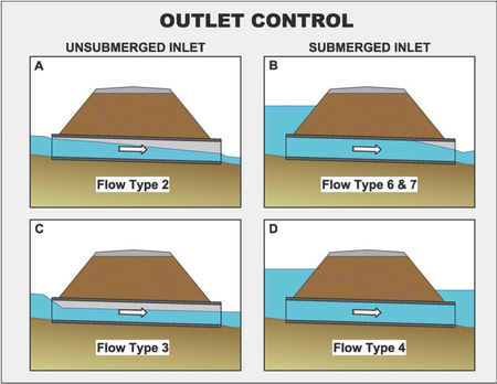
Outlet control means that the amount of water the culvert barrel can carry is limited by the barrel and/or tailwater conditions downstream. As a result, the flow in the barrel is subcritical, and the energy equation may be used to find the upstream headwater depth. Several flow profiles are possible as are shown below and as described in HDS-5. HY-8 flow types 2, 3, 4, 6, and 7 are all outlet control flow types and are shown in the figure below. The various flow type properties may be found in HY-8 by selecting the Flow Types button from the Culvert Summary Table and are shown below.
Outlet Control Computations
The logic for determining flow type due to outlet control is shown in the figure below:
This flowchart uses the following terms:
HJ = Check for Hydraulic Jumps
Full flow = Check if the culvert is flowing full
TWH = Depth of the tailwater from the invert of the tailwater channel at the culvert outlet
twOutletDepth = Depth of the tailwater from the invert of the culvert at the culvert outlet. If the culvert is buried, this value is taken from the top of the embedment material.
IH = Inlet control headwater depth measured at the inlet invert of the culvert
OH = Outlet control headwater depth measured at the inlet invert of the culvert
RISE = Height of the culvert. If the culvert is buried, this value is taken from the top of the embedment material.
Inlet Depth = The depth computed at the entrance to the culvert using the direct step profile computation method
Critical = The critical depth in the culvert
Normal = The normal depth in the culvert
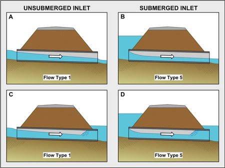
Inlet control means that the amount of water the culvert barrel can carry is limited by the culvert entrance. Flow passes through critical depth at the culvert entrance and is supercritical in the barrel. There are several flow profiles possible, HY-8 simulates so-called Type A, B, C, and D conditions as shown below and as described in HDS-5. These profiles are known as Type 1 (A, C) and Type 5 (B, D) within HY-8. The various flow type properties may be found in HY-8 by selecting the Flow Types button from the Culvert Summary Table and are shown below. Because the flow in the barrel is supercritical, outlet losses and friction losses are not reflected in the headwater elevation. The headwater elevation is a function of the entrance size, shape, slope, and culvert type. The computed inlet control headwater elevation is found by accessing the results of scaled physical model tests. The logic for determining what inlet flow control type prevails is shown below (from the original HY-8 help file).
Inlet Control Logic
Determine Applicable Inlet Control Equation
- IF circle or box with IMPROVED INLETS then use INLET equations.
- For Straight (previously called conventional) INLETS
- A. If Q is < Q at .5D, then assume LOW FLOW INLET CONTROL:
- i. calculate CRITICAL DEPTH (DCO)
- ii. calculate Section Properties
- iii. VH = (Q / AC)^2 / 64.4
- iv. IH = DCO * LMULT + (1 + KELOW) * VH * VHCOEF
- IF no Depression THEN IHI = IH + I1E
- For Depression, HF = IH and check head on CREST.
- B. If Q > Q at .5D, but < Q at 3D, then use INLET REGRESSION EQUATIONS.
- C. If Q > Q at 3D, then assume HIGH FLOW INLET CONTROL.
- i. IH = (Q / CDAHI)^2 + .5 * RISE
- ii. IF no Depression THEN IHI = IH + I1E
- For Depression, HF = IH and check head on CREST.
- A. If Q is < Q at .5D, then assume LOW FLOW INLET CONTROL:
Inlet Regression Equations (Q between Q at 0.5D and Q at 3D)
- CIRCULAR
- A. See Straight inlet equations
- B. SIDE TAPERED ELLIPTICAL TRANSITION, THROAT CONTROL
- ZZ = Q / SQR(RISE ^ 5), Y = LOG(ZZ) / 2.30258
- i. IF n < .015 THEN SMOOTH PIPE IMPROVRD INLET.
- ii. If n >=.015 then ROUGH PIPE IMPROVED INLET.
- iii. Calculate THROAT CONTROL
- iv. Calculate FACE CONTROL
- v. IF Depression Then CW = CWF, calculate CREST control.
- C. SIDE TAPERED RECTANGULAR TRANSITION or SLOPE TAPERED
- i. Calculate THROAT CONTROL
- ii. Calculate FACE CONTROL
- iii. IF Depression Then CW = CWF, calculate CREST control.
- BOX CULVERTS
- A. See Straight inlet equations
- B. SIDE TAPERED RECTANGULAR TRANSITION or SLOPE TAPERED
- i. Calculate THROAT CONTROL
- ii. Calculate FACE CONTROL
- iii. IF Depression Then CW = CWF, calculate CREST control.
- PIPE ARCHES AND ELLIPSES
- A. See Straight inlet equations
- IRREGULAR SHAPE
- A. See Straight inlet equations
Straight Inlet Equations
- For IRREGULAR shape, X = Q / (AC * SQR(RISE))
- IF X <= .5 THEN IH = (A(1) * (X / .5)) * RISE
- ELSE IH = (A(J - 1) + (A(J) - A(J - 1)) * ((X - J + 2) / INC)) * RISE
- For all others shapes, X = Q / (SPAN * SQR(RISE^3)): SR = SR(IC)
- IH = (A + (B + (C + (D + (E + F * X) * X) * X) * X) * X - SR * S0) * RISE
- Headwater elevation (IHI) = IH + I1E if no Depression.
- For Depression, CREST headwater is checked.
Throat Control Tapered Inlet
- X = Q / (SPAN * SQR(RISE^3))
- HT=RISE*(.1295033+(.3789944+(-.0437778+(4.26329E-03-1.06358E-04*X)*X)*X)*X)
Face Control-Side Tapered Inlet
- ZZ = Q / (BF * SQR(RISE^3))
- Calculate UNSUBMERGED: HF1 = (.56 * RISE) * (ZZ ^ .66667)
- Calculate SUBMERGED
- A. For bevels: HF3 = (.0378 * (ZZ * ZZ) + .86) * RISE
- IF HF1 > RISE THEN HF = HF3
- IF HF1 < RISE THEN HF = HF1
- IF HF1 >= HF3 THEN HF = HF1
- B. For other edges: HF2 = (.0446 * (ZZ * ZZ) + .84) * RISE
- IF HF1 > RISE THEN HF = HF2
- IF HF1 < RISE THEN HF = HF1
- IF HF1 >= HF2 THEN HF = HF1
- A. For bevels: HF3 = (.0378 * (ZZ * ZZ) + .86) * RISE
Face Control For Slope Tapered Inlet
- ZZ = Q / (BF * SQR(RISE^3))
- Calculate UNSUBMERGED: HF1 = (.5 * RISE) * (ZZ ^ .66667)
- A. For bevels: HF3 = (.0378 * (ZZ * ZZ) + .7) * RISE
- IF HF1 > RISE THEN HF = HF3
- IF HF1 < RISE THEN HF = HF1
- IF HF1 > HF3 THEN HF = HF1
- B. For other edges: HF2 = (.0446 * (ZZ * ZZ) + .64) * RISE
- IF HF1 > RISE THEN HF = HF2
- IF HF1 < RISE THEN HF = HF1
- IF HF1 > HF2 THEN HF = HF1
- A. For bevels: HF3 = (.0378 * (ZZ * ZZ) + .7) * RISE
Crest ControlL
- HC = .5 * (Q / CW) ^ .66667
Outlet Control Procedures That Produce an Inlet Control Profile
STEP
- Compute critical depth (dco)
- Compute normal depth (dno)
- Compute fullflow if nomograph solution assumed "6-FFt or FFc".
- If dno > .95(rise), assume fullflow "6-FFn".
- If dno > dco, assume mild slope (SEE OUTLET.DAT).
- If dno <= dco, assume steep slope.
- A. If twh is >= So(L) + rise, assume fullflow "4-FFt".\
- B. If twh is >= rise, outlet submerged, assume inlet unsubmerged.
- C. If twh is < rise, outlet is unsubmerged, assume inlet unsubmerged.
- i. Assume headwater (oh) = inlet control headwater (ih)
- Calculate S2 curve "1-S2n" for outlet depth.
- If oh >= rise, inlet submerged "5-S2n"
- ii. If twh > headwater, tailwater drowns out jump.
- Calculate M1 curve "3-M1t".
- If culvert flows part full, "7-Mit".
- i. Assume headwater (oh) = inlet control headwater (ih)


