HY8:Straight Drop Structure: Difference between revisions
From XMS Wiki
Jump to navigationJump to search
No edit summary |
m (Jcreer moved page HY-8:Straight Drop Structure to HY8:Straight Drop Structure) |
||
| (5 intermediate revisions by 2 users not shown) | |||
| Line 1: | Line 1: | ||
The input variables required for this calculation is the following: | The input variables required for this calculation is the following: | ||
Drop Height | *Drop Height — The vertical drop height from structure crest to channel bottom. In the final design, the drop height to the basin bottom is given. The difference between the two is the amount the basin is suppressed below the channel bottom. | ||
*New Slope — The slope that will exist on the channel once the drop structures are in place (the new slope must be subcritical). | |||
New Slope | |||
The following figures show straight drop structures. | The following figures show straight drop structures. | ||
[[Image:HY8image20.jpg]] | [[Image:HY8image20.jpg]] | ||
Variables from the figure | Variables from the figure | ||
* q | * q — Design Discharge | ||
* y<sub>c</sub> | * y<sub>c</sub> — Critical depth | ||
* h<sub>0</sub> | * h<sub>0</sub> — Drop from crest to stilling basin floor | ||
* y<sub>1</sub> | * y<sub>1</sub> — Pool depth under the nappe | ||
* y<sub>2</sub> | * y<sub>2</sub> — Depth of flow at the tow of the nappe or the beginning of the hydraulic jump | ||
* y<sub>3</sub> | * y<sub>3</sub> — Tailwater depth sequent to y2 | ||
* L<sub>1</sub> | * L<sub>1</sub> — Distance from the headwall to the point where the surface of the upper nappe strikes the stilling basin floor | ||
* L<sub>2</sub> | * L<sub>2</sub> — Distance from the upstream face of the floor blocks to the end of the stilling basin | ||
[[Image:HY8image21.jpg]] | [[Image:HY8image21.jpg]] | ||
| Line 27: | Line 23: | ||
Variables from the figure | Variables from the figure | ||
* y<sub>c</sub> | * y<sub>c</sub> — Critical depth | ||
* h<sub>0</sub> | * h<sub>0</sub> — Drop from crest to stilling basin floor | ||
* h | * h — Vertical drop between the approach and tailwater channels | ||
* y<sub>1</sub> | * y<sub>1</sub> — Pool depth under the nappe | ||
* y<sub>2</sub> | * y<sub>2</sub> — Depth of flow at the tow of the nappe or the beginning of the hydraulic jump | ||
* y<sub>3</sub> | * y<sub>3</sub> — Tailwater depth sequent to y2 | ||
* L<sub>1</sub> | * L<sub>1</sub> — Distance from the headwall to the point where the surface of the upper nappe strikes the stilling basin floor | ||
* L<sub>2</sub> | * L<sub>2</sub> — Distance from the upstream face of the floor blocks to the end of the stilling basin | ||
* L<sub>3</sub> | * L<sub>3</sub> — distance from the upstream face of the floor blocks to the end of the stilling basin | ||
* L<sub> | * L<sub>B</sub> — Stilling basin length | ||
{{HY8Main}} | {{HY8Main}} | ||
[[Category:Energy Dissipators|S]] | |||
Latest revision as of 14:51, 10 October 2016
The input variables required for this calculation is the following:
- Drop Height — The vertical drop height from structure crest to channel bottom. In the final design, the drop height to the basin bottom is given. The difference between the two is the amount the basin is suppressed below the channel bottom.
- New Slope — The slope that will exist on the channel once the drop structures are in place (the new slope must be subcritical).
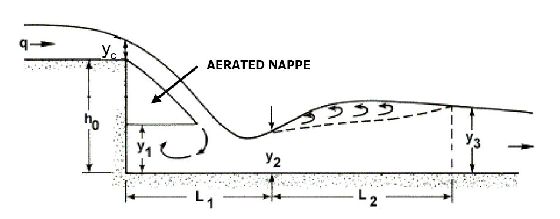
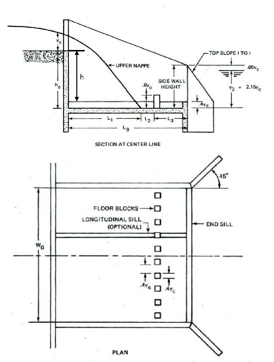
The following figures show straight drop structures.
Variables from the figure
- q — Design Discharge
- yc — Critical depth
- h0 — Drop from crest to stilling basin floor
- y1 — Pool depth under the nappe
- y2 — Depth of flow at the tow of the nappe or the beginning of the hydraulic jump
- y3 — Tailwater depth sequent to y2
- L1 — Distance from the headwall to the point where the surface of the upper nappe strikes the stilling basin floor
- L2 — Distance from the upstream face of the floor blocks to the end of the stilling basin
Variables from the figure
- yc — Critical depth
- h0 — Drop from crest to stilling basin floor
- h — Vertical drop between the approach and tailwater channels
- y1 — Pool depth under the nappe
- y2 — Depth of flow at the tow of the nappe or the beginning of the hydraulic jump
- y3 — Tailwater depth sequent to y2
- L1 — Distance from the headwall to the point where the surface of the upper nappe strikes the stilling basin floor
- L2 — Distance from the upstream face of the floor blocks to the end of the stilling basin
- L3 — distance from the upstream face of the floor blocks to the end of the stilling basin
- LB — Stilling basin length

