HY8:Inlet Configurations: Difference between revisions
From XMS Wiki
Jump to navigationJump to search
No edit summary |
No edit summary |
||
| (8 intermediate revisions by 2 users not shown) | |||
| Line 1: | Line 1: | ||
Select from the following inlet configurations which are available according to the selected culvert shape. The following inlet conditions are available (see drawing), but may not apply to all shapes or materials: | |||
*Projecting | *Projecting | ||
| Line 8: | Line 8: | ||
*Mitered to conform with fill slope | *Mitered to conform with fill slope | ||
*Headwall | *Headwall | ||
*Wingwalls | |||
| Line 16: | Line 17: | ||
{| Border=2 CellPadding=5 CellSpacing=2 | {| Border=2 CellPadding=5 CellSpacing=2 | ||
|- | |- | ||
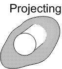
| Width=263 Align=Center | [[Image:HY8Projecting.jpg]] || Width=130 Valign=Center | This | | Width=263 Align=Center | [[Image:HY8Projecting.jpg]] || Width=130 Valign=Center | This configuration results in the end of the culvert barrel projecting out of the embankment. | ||
|- | |- | ||
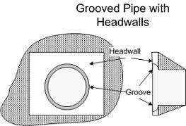
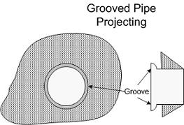
| Align=Center | [[Image:HY8GroovedHeadWall(FINAL).JPG]] || Valign=Center | The grooved pipe is for concrete culverts and decreases the loss through the culvert entrance. | | Align=Center | [[Image:HY8GroovedHeadWall(FINAL).JPG]] || Valign=Center | The grooved pipe is for concrete culverts and decreases the loss through the culvert entrance. | ||
| Line 24: | Line 25: | ||
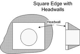
| Align=Center | [[Image:HY8SquareEdgeHeadWall(FINAL).JPG]] || Valign=Center | Square edge with headwall is an entrance condition where the culvert entrance is flush with the headwall. | | Align=Center | [[Image:HY8SquareEdgeHeadWall(FINAL).JPG]] || Valign=Center | Square edge with headwall is an entrance condition where the culvert entrance is flush with the headwall. | ||
|- | |- | ||
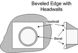
| Align=Center | [[Image:HY8BevelEdgeHeadWall(FINAL).JPG]] || Valign=Center | 'Beveled edges' is | | Align=Center | [[Image:HY8BevelEdgeHeadWall(FINAL).JPG]] || Valign=Center | 'Beveled edges' is a tapered inlet edge that decreases head loss as flow enters the culvert barrel. | ||
|- | |- | ||
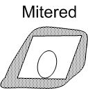
| Align=Center | [[Image:HY8Mitered.jpg]] || Valign=Center | A mitered entrance is when the culvert barrel is cut so it is flush with the embankment slope. | | Align=Center | [[Image:HY8Mitered.jpg]] || Valign=Center | A mitered entrance is when the culvert barrel is cut so it is flush with the embankment slope. | ||
|- | |- | ||
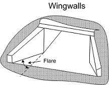
| Align=Center | [[Image:HY8Wingwalls(FINAL).JPG]] || Valign=Center | Wingwalls are used when the culvert is shorter than the embankment and prevents embankment material from falling into the culvert | | Align=Center | [[Image:HY8Wingwalls(FINAL).JPG]] || Valign=Center | Wingwalls are used when the culvert is shorter than the embankment and prevents embankment material from falling into the culvert. | ||
|} | |} | ||
| Line 35: | Line 36: | ||
{{ | {{HY8Main}} | ||
[[Category:Culvert Data|I]] | |||
Latest revision as of 21:32, 28 February 2018
Select from the following inlet configurations which are available according to the selected culvert shape. The following inlet conditions are available (see drawing), but may not apply to all shapes or materials:
- Projecting
- Grooved end with headwall (0.05 X 0.07D)
- Grooved end projecting (0.05 X 0.07D)
- Square edge with headwall
- Beveled
- Mitered to conform with fill slope
- Headwall
- Wingwalls
The user can select only one inlet condition for each culvert. Detailed explanations of these inlet conditions can be found in FHWA Publication HDS No. 5 (2001) bundled with the program.
- NOTE: HDS-5 notes that "Flared end sections made of either metal or concrete, are the sections commonly available from manufacturers. From limited hydraulic tests they are equivalent in operation to a headwall in both inlet and outlet control. Some end sections, incorporating a closed taper in their design have a superior hydraulic performance. These latter sections can be designed using the information given for the beveled inlet"
