CW:CityWater Project Map: Difference between revisions
No edit summary |
|||
| (33 intermediate revisions by 4 users not shown) | |||
| Line 7: | Line 7: | ||
* To zoom in or out, use the [[File:CityWaterMapZoom.png|16 px]] and [[File:CityWaterMapZoomOut.png|16 px]] buttons in the top left-hand corner of the map or use the mouse scroll wheel. | * To zoom in or out, use the [[File:CityWaterMapZoom.png|16 px]] and [[File:CityWaterMapZoomOut.png|16 px]] buttons in the top left-hand corner of the map or use the mouse scroll wheel. | ||
* Hold the Shift key while clicking and dragging the mouse to box zoom. | * Hold the Shift key while clicking and dragging the mouse to box zoom. | ||
* To frame the model extents on the map, use the '''Zoom to Extent''' [[File:TethyZoomToExtentsIcon.png|24 px]] button in the bottom right hand corner of the screen. | * To frame the model extents on the map, use the '''Zoom to Extent''' [[File:TethyZoomToExtentsIcon.png|24 px]] button in the bottom right-hand corner of the screen. | ||
* The search field can be used the same as in Google Maps or Bing Maps. Addresses, landmarks, coordinates, and other search terms are acceptable. It will not find locations specific to the EPANET network such as links, nodes, or tanks. | * The search field can be used the same as in Google Maps or Bing Maps. Addresses, landmarks, coordinates, and other search terms are acceptable. It will not find locations specific to the EPANET network such as links, nodes, or tanks. | ||
* The Base Map drop-down menu can be used to change the underlying map to one of the following: | * The Base Map drop-down menu can be used to change the underlying map to one of the following: | ||
| Line 15: | Line 15: | ||
===Jump To=== | ===Jump To=== | ||
To zoom in on a specific node or link, the Jump to Node and Jump to Link options can be used. Enter the Label ID in the field. The field is case sensitive and the Label must be entered exactly as shown in the Label field for the node or link properties. | To zoom in on a specific node or link, the Jump to Node and Jump to Link options can be used. These fields are located at the bottom of the page. Enter the Label ID in the field or select the link or node from the drop-down list. The field is case sensitive and the Label must be entered exactly as shown in the Label field for the node or link properties. | ||
==Map Legend== | ==Map Legend== | ||
In the lower right corner, the legend is shown. The legend shows the element symbols being displayed | [[File:Map_Legend_CityWater.PNG |thumb|500 px|Example of the Map Legend]] | ||
In the lower right corner, the legend is shown. The legend shows the element symbols being displayed on the map. Values shown in the legend depends on the options selected in the Layers tab on the left side of the screen. Values in the legend can be hidden by clicking on the down arrow [[File:CityWaterLegendArrow.png|14 px]] next to the value category name. | |||
'''''Legend''''' – Lists the different factors being depicted within the map through the use of representative symbols. | |||
*Tank – A Tank is represented by a large square symbol on the map and is an area built for water to be stored. | |||
*Reservoirs – A reservoir is represented by a large triangle on the map and is a natural body of stored water. | |||
*Junctions – Junctions are represented by small dots on the map and are areas where the water pipes meet for the flow of water. | |||
*Pipes – Pipes are represented by a thick line and are built mechanisms that help carry water throughout the city. | |||
*Pumps – Pumps are represented by this symbol [[File:Pumps_CityWater.PNG|18 px]] and are places that control the flow of water. | |||
*Valves – Valves are represented by this symbol [[File:Valves_CityWater.PNG|18 px]] and are ways to start and stop the flow of water. | |||
'''''Pressure (psi)''''' | |||
The pressure is represented through various colored dots on the map including dark blue, light blue, green, yellow, and red. Each one of these colors indicates a different water pressure that is shown on the map legend. | |||
'''''Velocity (fps)''''' | |||
The velocity is indicated as different colored lines including dark blue, light blue, green, yellow, and red throughout the map that show the different velocities being represented. These velocities are listed in the map legend. | |||
<!--removed | |||
==Water Quality Options== | ==Water Quality Options== | ||
| Line 24: | Line 48: | ||
[[File:CityWaterWaterQualityOptions.png|thumb|none|400 px|Example of the Water Quality Options dialog]] | [[File:CityWaterWaterQualityOptions.png|thumb|none|400 px|Example of the Water Quality Options dialog]] | ||
--> | |||
==Fire Flow Options== | ==Fire Flow Options== | ||
A peakday fire flow analysis can be performed at project upload if desired. This will create a new map layer with color-coded nodes according to the peakday fire flow available at each node based on the peakday time and residual pressure specified by the user. | This option is only available if the account includes the Fire Flow Analysis add-on. | ||
A peakday fire flow analysis can be performed at project upload if desired using an account above the standard subscription level. This will create a new map layer with color-coded nodes according to the peakday fire flow available at each node based on the peakday time and residual pressure specified by the user. | |||
From the toolbar in the map, you can get the available flow at any node in the model. This is based on the specified time step and the nozzle size chosen. | From the toolbar in the map, you can get the available flow at any node in the model. This is based on the specified time step and the nozzle size chosen. | ||
Also from the toolbar, you can select the '''Fire Flow Options''' [[File:TethyFireFlowOptionsIcon.png|24 px]] button. This brings up the Fire Flow Options dialog where you can input | Also from the toolbar, you can select the '''Fire Flow Options''' [[File:TethyFireFlowOptionsIcon.png|24 px]] button. This brings up the Fire Flow Options dialog where you can input the desired flow, residual pressure, and duration to generate results showing if any nodes in the zone violate this residual pressure. | ||
[[File:CityWaterFireFlowOptions.png|thumb|none|400 px|Example of the Fire Flow Options dialog]] | [[File:CityWaterFireFlowOptions.png|thumb|none|400 px|Example of the Fire Flow Options dialog]] | ||
| Line 46: | Line 73: | ||
==Layers Selection== | ==Layers Selection== | ||
The Layers tab, in the lower left portion of the window, allows selecting which attributes to display in the map area. | The Layers tab, in the lower-left portion of the window, allows selecting which attributes to display in the map area. | ||
There are several different layers that you can view on the map. You can toggle through the different layers using the Layer controls. | There are several different layers that you can view on the map. You can toggle through the different layers using the Layer controls. | ||
#Select the Layers tab from the left hand panel to access e Layer controls. If the left hand panel is hidden, you can show it by using the [[File:Panel Menu Icon.png| | #Select the Layers tab from the left-hand panel to access e Layer controls. If the left-hand panel is hidden, you can show it by using the [[File:Panel Menu Icon.png|14 px]] menu button, located in the top left-hand corner of the page. | ||
#Select Node from the Node | #Select Node from the Node Layer drop-down menu and Links from the Link Layer drop-down menu. | ||
Notice how the symbology on the map and legend change. The Node and Link layers represent the network geometry with no simulation result values symbolized, which is why all the nodes and links are white. | Notice how the symbology on the map and legend change. The Node and Link layers represent the network geometry with no simulation result values symbolized, which is why all the nodes and links are white. | ||
Map layers reflect average values by default (if no specific time step is selected). While in this configuration, selecting a feature will display the average, maximum, and minimum values. | The Labels toggle under the Node Layer and Link Layer drop-down menus will display the value for the selected layer. For example, if the Pressure layer is selected for the Node Layer and the Labels options are turned on, the pressure value will be displayed next to each node on the map. | ||
The Time options allow which set of values over time are displayed. The time values are averaged by default, however, the maximum or minimum time values can be displayed instead. | |||
<!--outdated info? Map layers reflect average values by default (if no specific time step is selected). While in this configuration, selecting a feature will display the average, maximum, and minimum values.--> | |||
==Properties== | ==Properties== | ||
Latest revision as of 21:37, 14 May 2020
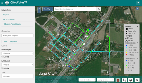
The Map page displays an aerial map of the project area with the pipe network overlaying the area. This page can be reached from either the Projects page or the Project Details page using the Map tab.
Map navigation similar to other mapping applications:
- To zoom in or out, use the
 and
and  buttons in the top left-hand corner of the map or use the mouse scroll wheel.
 - Hold the Shift key while clicking and dragging the mouse to box zoom.
- To frame the model extents on the map, use the Zoom to Extent
 button in the bottom right-hand corner of the screen.
 - The search field can be used the same as in Google Maps or Bing Maps. Addresses, landmarks, coordinates, and other search terms are acceptable. It will not find locations specific to the EPANET network such as links, nodes, or tanks.
- The Base Map drop-down menu can be used to change the underlying map to one of the following:
- Aerial w/Label – Shows an aerial map with roads and other features labeled.
- Aerial – Shows a simple aerial map. Roads and other features are not labeled.
- Road – Shows a standard road map with streets labeled, but topographic features are removed.
Jump To
To zoom in on a specific node or link, the Jump to Node and Jump to Link options can be used. These fields are located at the bottom of the page. Enter the Label ID in the field or select the link or node from the drop-down list. The field is case sensitive and the Label must be entered exactly as shown in the Label field for the node or link properties.
Map Legend
In the lower right corner, the legend is shown. The legend shows the element symbols being displayed on the map. Values shown in the legend depends on the options selected in the Layers tab on the left side of the screen. Values in the legend can be hidden by clicking on the down arrow ![]() next to the value category name.
next to the value category name.
Legend – Lists the different factors being depicted within the map through the use of representative symbols.
- Tank – A Tank is represented by a large square symbol on the map and is an area built for water to be stored.
- Reservoirs – A reservoir is represented by a large triangle on the map and is a natural body of stored water.
- Junctions – Junctions are represented by small dots on the map and are areas where the water pipes meet for the flow of water.
- Pipes – Pipes are represented by a thick line and are built mechanisms that help carry water throughout the city.
Pressure (psi)
The pressure is represented through various colored dots on the map including dark blue, light blue, green, yellow, and red. Each one of these colors indicates a different water pressure that is shown on the map legend.
Velocity (fps)
The velocity is indicated as different colored lines including dark blue, light blue, green, yellow, and red throughout the map that show the different velocities being represented. These velocities are listed in the map legend.
Fire Flow Options
This option is only available if the account includes the Fire Flow Analysis add-on.
A peakday fire flow analysis can be performed at project upload if desired using an account above the standard subscription level. This will create a new map layer with color-coded nodes according to the peakday fire flow available at each node based on the peakday time and residual pressure specified by the user.
From the toolbar in the map, you can get the available flow at any node in the model. This is based on the specified time step and the nozzle size chosen.
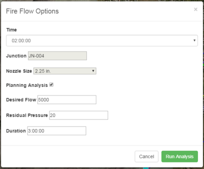
Also from the toolbar, you can select the Fire Flow Options ![]() button. This brings up the Fire Flow Options dialog where you can input the desired flow, residual pressure, and duration to generate results showing if any nodes in the zone violate this residual pressure.
button. This brings up the Fire Flow Options dialog where you can input the desired flow, residual pressure, and duration to generate results showing if any nodes in the zone violate this residual pressure.
Plot
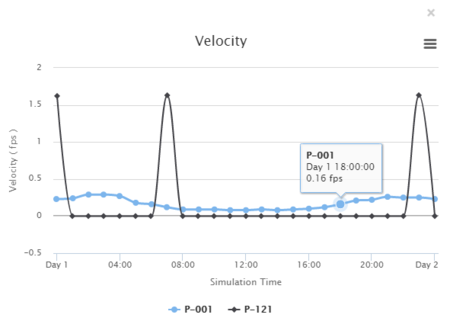
When an element has been selected, CityWater can generate a plot based on the element temporal properties. Clicking the Plot ![]() button will bring up a plot on the lower half of the screen. This will display a plot of the variable versus time for the selected element. If you select multiple elements and press the Plot
button will bring up a plot on the lower half of the screen. This will display a plot of the variable versus time for the selected element. If you select multiple elements and press the Plot ![]() button, a time series for each selected element will be plotted.
button, a time series for each selected element will be plotted.
Using your mouse to roll over specific plot points will bring up a dialog showing the values for the plot point.
Plots can be exported as an image. Clicking the menu ![]() button in the corner of the plot will bring up export options. Plots can be saved in PNG, JPEG, PDF, or SVG file formats.
button in the corner of the plot will bring up export options. Plots can be saved in PNG, JPEG, PDF, or SVG file formats.
Animate Layers
Clicking the ![]() button will create an animation of all time steps in the simulation. This is only available if the model is not a steady-state, snapshot model.
button will create an animation of all time steps in the simulation. This is only available if the model is not a steady-state, snapshot model.
Layers Selection
The Layers tab, in the lower-left portion of the window, allows selecting which attributes to display in the map area.
There are several different layers that you can view on the map. You can toggle through the different layers using the Layer controls.
- Select the Layers tab from the left-hand panel to access e Layer controls. If the left-hand panel is hidden, you can show it by using the
 menu button, located in the top left-hand corner of the page.
 - Select Node from the Node Layer drop-down menu and Links from the Link Layer drop-down menu.
Notice how the symbology on the map and legend change. The Node and Link layers represent the network geometry with no simulation result values symbolized, which is why all the nodes and links are white.
The Labels toggle under the Node Layer and Link Layer drop-down menus will display the value for the selected layer. For example, if the Pressure layer is selected for the Node Layer and the Labels options are turned on, the pressure value will be displayed next to each node on the map.
The Time options allow which set of values over time are displayed. The time values are averaged by default, however, the maximum or minimum time values can be displayed instead.
Properties
After selecting a feature, the Properties tab on the lower left side of the screen will display the values associated with the feature. The table below shows typical values displayed for each feature.
| Feature | Junctions | Pipe | Pump | Reservoirs | Tank | Valves |
|---|---|---|---|---|---|---|
| Values |
|
|
|
|
|
|
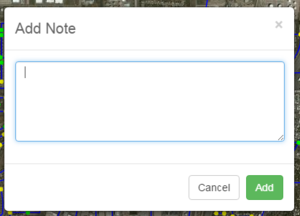
Add a note to any element by selecting it and pressing the Add button next to the Note property in the Properties tab on the left. Enter your note in the Add Note dialog that appears and press the Add button to save it.
View all of the annotations on the map by going back to the Project Details page and selecting the Map tab. The annotations are listed based on element type. Use the search boxes to find specific annotations.
Related Topics
CityWater | ||
|---|---|---|
| Articles: | Overview • Project Details • Project Map • Project Schematic • Scenarios • User Management |  |
| Support: | Tutorials • Convert NET File • What's New in CityWater • Release Notes • Terms and Conditions | |
| Aquaveo | ||


