HY8:Culvert Type: Difference between revisions
No edit summary |
No edit summary |
||
| Line 6: | Line 6: | ||
*'''[[WMS:HY-8_Broken_Back_Culverts|Single Broken-back]]''' | *'''[[WMS:HY-8_Broken_Back_Culverts|Single Broken-back]]''' | ||
*'''[[WMS:HY-8_Broken_Back_Culverts|Double Broken-back]]''' | *'''[[WMS:HY-8_Broken_Back_Culverts|Double Broken-back]]''' | ||
==Conventional== | ==Conventional== | ||
Conventional inlets are those for which no special or additional modification is made by the manufacturer or when constructed in the field. Conventional inlets for corrugated metal pipes (CMP) include thin edge projecting, pipes mitered to conform to the fill slope, or pipes with a headwall. Conventional inlets for concrete pipes and boxes include the standard groove-end section (pipe only), and inlets with a headwall and/or wingwall. Flared end sections fit to either CMP or concrete are also considered conventional inlets. Since beveling the entrance is so common, a beveled entrance appears on the conventional inlet menu for HY-8, but a beveled inlet is technically called an improved inlet. | Conventional inlets are those for which no special or additional modification is made by the manufacturer or when constructed in the field. Conventional inlets for corrugated metal pipes (CMP) include thin edge projecting, pipes mitered to conform to the fill slope, or pipes with a headwall. Conventional inlets for concrete pipes and boxes include the standard groove-end section (pipe only), and inlets with a headwall and/or wingwall. Flared end sections fit to either CMP or concrete are also considered conventional inlets. Since beveling the entrance is so common, a beveled entrance appears on the conventional inlet menu for HY-8, but a beveled inlet is technically called an improved inlet. | ||
==Side Tapered== | ==Side Tapered== | ||
| Line 25: | Line 21: | ||
*'''Face Height''' -- Shown as Hf in the drawing below, can be no smaller than the barrel height and no larger than 1.1 times the barrel height. | *'''Face Height''' -- Shown as Hf in the drawing below, can be no smaller than the barrel height and no larger than 1.1 times the barrel height. | ||
A side-tapered, rectangular inlet has an enlarged rectangular face section with transition (taper) to the culvert barrel. The side-tapered dimensions are entered as follows: | A side-tapered, rectangular inlet has an enlarged rectangular face section with transition (taper) to the culvert barrel. The side-tapered dimensions are entered as follows: | ||
| Line 33: | Line 28: | ||
*'''Side Taper''' -- (4:1 to 6:1) (_:1) flare of walls of rectangular transition. Value that is input should be the number of units of wall length for every 1 unit of flare. | *'''Side Taper''' -- (4:1 to 6:1) (_:1) flare of walls of rectangular transition. Value that is input should be the number of units of wall length for every 1 unit of flare. | ||
If the selected face width is not wide enough the face section will produce a higher headwater elevation than the culvert throat as shown in the “Improved Inlet Table.” The user must continue to increase the face width and run the analysis until the headwater depth ceases to change with increasing face width. Once this occurs the face section no longer controls and may be used in analysis and construction. Detailed information pertaining to side-tapered inlets can be found in FHWA Publication HDS NO. 5 (2001), bundled with the HY-8 program and accessed from the Help menu. | If the selected face width is not wide enough the face section will produce a higher headwater elevation than the culvert throat as shown in the “Improved Inlet Table.” The user must continue to increase the face width and run the analysis until the headwater depth ceases to change with increasing face width. Once this occurs the face section no longer controls and may be used in analysis and construction. Detailed information pertaining to side-tapered inlets can be found in FHWA Publication HDS NO. 5 (2001), bundled with the HY-8 program and accessed from the Help menu. | ||
[[Image:HY8SideTapered(SMALL).jpg]] | [[Image:HY8SideTapered(SMALL).jpg]] | ||
==Slope Tapered== | ==Slope Tapered== | ||
A slope tapered inlet is an improved inlet used to increase the culvert performance by providing fall and a more efficient control section at the throat, designated to represent the location of the culvert where a constant size begins (see drawing below). Slope tapered dimensions are entered as follows: | A slope tapered inlet is an improved inlet used to increase the culvert performance by providing fall and a more efficient control section at the throat, designated to represent the location of the culvert where a constant size begins (see drawing below). Slope tapered dimensions are entered as follows: | ||
*'''Face Width''' -- Width of enlarged face section, denoted Wf in the drawing below. | *'''Face Width''' -- Width of enlarged face section, denoted Wf in the drawing below. | ||
| Line 60: | Line 49: | ||
*'''Crest Length''' -- Length of the upstream paved crest at the stream bed. This length is only used when the culvert face is mitered. | *'''Crest Length''' -- Length of the upstream paved crest at the stream bed. This length is only used when the culvert face is mitered. | ||
If the selected face width (and crest width in the case of a mitered face) is not wide enough the face (or crest) section will produce a higher headwater elevation than the culvert throat. The user must continue to increase the face width (and/or the crest width in the case of a mitered face) and run the analysis until the headwater depth ceases to change with increasing face width (and crest width in the case of a mitered face). Once this occurs the face section (and/or the crest section) no longer controls and may be used in analysis and construction. Detailed information pertaining to slope tapered inlets can be found in FHWA Publication HDS NO. 5 (2001)and accessed from the Help menu. | If the selected face width (and crest width in the case of a mitered face) is not wide enough the face (or crest) section will produce a higher headwater elevation than the culvert throat. The user must continue to increase the face width (and/or the crest width in the case of a mitered face) and run the analysis until the headwater depth ceases to change with increasing face width (and crest width in the case of a mitered face). Once this occurs the face section (and/or the crest section) no longer controls and may be used in analysis and construction. Detailed information pertaining to slope tapered inlets can be found in FHWA Publication HDS NO. 5 (2001)and accessed from the Help menu. | ||
Revision as of 16:02, 6 October 2011
Five culvert inlet types are supported in HY-8:
- Conventional
- Side Tapered
- Slope Tapered
- Single Broken-back
- Double Broken-back
Conventional
Conventional inlets are those for which no special or additional modification is made by the manufacturer or when constructed in the field. Conventional inlets for corrugated metal pipes (CMP) include thin edge projecting, pipes mitered to conform to the fill slope, or pipes with a headwall. Conventional inlets for concrete pipes and boxes include the standard groove-end section (pipe only), and inlets with a headwall and/or wingwall. Flared end sections fit to either CMP or concrete are also considered conventional inlets. Since beveling the entrance is so common, a beveled entrance appears on the conventional inlet menu for HY-8, but a beveled inlet is technically called an improved inlet.
Side Tapered
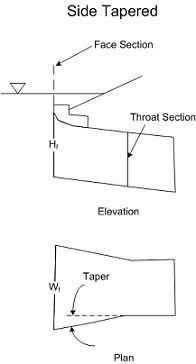
The side tapered option is available for circular or box culverts and is shown below. A side-tapered inlet is an improved inlet used to increase culvert performance by providing a more efficient inlet control section. A side-tapered, circular inlet has an enlarged elliptical face section with a transition (taper) to the circular culvert barrel. The side-tapered dimensions are entered as follows:
- Face Width -- Width of enlarged face section, denoted Wf in the drawing below.
- Side Taper -- (4:1 to 6:1) (_:1) Flare of walls of circular transition. Value that is input should be the number of units of wall length for every 1 unit of flare.
- Face Height -- Shown as Hf in the drawing below, can be no smaller than the barrel height and no larger than 1.1 times the barrel height.
A side-tapered, rectangular inlet has an enlarged rectangular face section with transition (taper) to the culvert barrel. The side-tapered dimensions are entered as follows:
- Face Width -- width of enlarged face section.
- Side Taper -- (4:1 to 6:1) (_:1) flare of walls of rectangular transition. Value that is input should be the number of units of wall length for every 1 unit of flare.
If the selected face width is not wide enough the face section will produce a higher headwater elevation than the culvert throat as shown in the “Improved Inlet Table.” The user must continue to increase the face width and run the analysis until the headwater depth ceases to change with increasing face width. Once this occurs the face section no longer controls and may be used in analysis and construction. Detailed information pertaining to side-tapered inlets can be found in FHWA Publication HDS NO. 5 (2001), bundled with the HY-8 program and accessed from the Help menu.
Slope Tapered
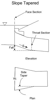
A slope tapered inlet is an improved inlet used to increase the culvert performance by providing fall and a more efficient control section at the throat, designated to represent the location of the culvert where a constant size begins (see drawing below). Slope tapered dimensions are entered as follows:
- Face Width -- Width of enlarged face section, denoted Wf in the drawing below.
- Side Taper -- (4:1 to 6:1) (_:1) Slope of walls of tapered transition. Value that is input should be the number of units of wall length for every 1 unit of flare.
- Fall Slope -- (2:1 to 3:1) (_:1) Slope between the entrance and throat invert, shown as St in the drawing below.
- Fall -- Depression of inlet control section below stream bed. Measured from stream bed to throat invert.
- Mitered Face (Y/N) -- Face of culvert cut to conform to embankment slope.
- Crest Length -- Length of the upstream paved crest at the stream bed. This length is only used when the culvert face is mitered.
If the selected face width (and crest width in the case of a mitered face) is not wide enough the face (or crest) section will produce a higher headwater elevation than the culvert throat. The user must continue to increase the face width (and/or the crest width in the case of a mitered face) and run the analysis until the headwater depth ceases to change with increasing face width (and crest width in the case of a mitered face). Once this occurs the face section (and/or the crest section) no longer controls and may be used in analysis and construction. Detailed information pertaining to slope tapered inlets can be found in FHWA Publication HDS NO. 5 (2001)and accessed from the Help menu.

