HY8:Tumbling Flow: Difference between revisions
| Line 8: | Line 8: | ||
The following figures show two configurations of tumbling flow dissipators. | The following figures show two configurations of tumbling flow dissipators. | ||
[[Image:HY8image11.jpg|500 px]] | [[Image:HY8image11.jpg|thumb|none|500 px|Figure 1]] | ||
Variables from the | Variables from the Figure 1: | ||
* L — Length from beginning of one roughness element to the beginning of the next roughness element. | * L — Length from beginning of one roughness element to the beginning of the next roughness element. | ||
Revision as of 15:51, 1 December 2016
Tumbling Flow in Box Culverts
The input variables required for this calculation is the following:
Roughness Spacing to Height Ratio — The user must select a value of either 8.5 or 10 for the ratio of roughness element spacing divided by roughness element height. If after calculations the flow through the roughened section of the culvert impacts on the culvert roof, then the minimum enlarged section height needed to correct this problem will be given and the user will be prompted to enter a value equal to or larger than this minimum value.
Height, which must be equal to or greater than the height of the culvert.
The following figures show two configurations of tumbling flow dissipators.
Variables from the Figure 1:
- L — Length from beginning of one roughness element to the beginning of the next roughness element.
- h — Height of roughness element
- h1 — Distance from top of dissipator to ceiling of culvert
- h2 — Height of splash shield on ceiling of culvert
- h3 — Culvert rise
- yn — Tailwater depth
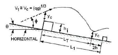
Variables from the figure:
- L1 — Length from beginning of one roughness element to the beginning of the next roughness element.
- LT — Transition Length
- hi — Height of roughness element
- yc — Critical depth
- θ — slope of the culvert bottom expressed in degrees
- φ — jet angle, taken as 45 degrees
Tumbling Flow in Circular Culverts
The only input variable required for this calculation is the following:
- Diameter of enlarged culvert
The following figures show implementations of tumbling flow within circular culverts along with the variables used to design the energy dissipator.
Variables from the figure
- D — Diameter of original culvert
- Vn — Tailwater velocity
- yn — Tailwater depth
- L — Length from beginning of one roughness element to the beginning of the next roughness element.
- h — Height of roughness element
- h1 — length from top of roughness element to enlarged culvert ceiling
- h2 — height of splash shield on enlarged culvert ceiling.
- h3 — rise of enlarged culvert.
Variables from the figure
- D — Diameter of original culvert
- D1 — Diameter of enlarged culvert
- Di — Diameter of roughened section
- h — Height of roughness element
- L — Length from beginning of one roughness element to the beginning of the next roughness element.
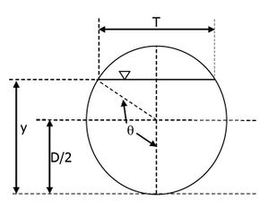
Variables from the figure
- D — Diameter of original culvert
- T — Water surface width at critical flow condition
- y — Depth of flow


