Raster Options: Difference between revisions
From XMS Wiki
Jump to navigationJump to search
No edit summary |
No edit summary |
||
| Line 22: | Line 22: | ||
|} | |} | ||
''' | ''' | ||
'''How to export TINs in adf format from ArcGIS in a format that WMS will read''' | |||
#Load the TIN into ArcMap | |||
#Expand the “3D Analyst Tools | Conversion Tools | From TIN” toolset in ArcToolbox | |||
#Double click the “TIN to Raster” tool in ArcToolbox (specify your current TIN file in the "Input TIN” field). Make a note of the path in the "Output Raster" field. | |||
#Expand the “Conversion Tools | From Raster” toolset in ArcToolbox | |||
#Double click the “Raster to ASCII” tool in ArcToolbox (specify the raster file that you created in the previous step as the input raster, and make a note of the path for the output file) | |||
#Open Windows Explorer (My Computer) and browse to the location of the ASCII .txt file output in step 5 | |||
#Make a copy of the *.txt file created in step 5 | |||
#Change the extension of the *.txt file to *.dem | |||
#Open the “.dem” file in WMS | |||
== Displaying Rasters == | == Displaying Rasters == | ||
Revision as of 17:34, 2 April 2012
Importing Rasters
Import a raster file by selecting Open in the File menu. Select the proper raster file as shown in the following table. Select Open. At the popup "Load it as...", select DEM.
| Format | File to Open | Source | Importance | Level of Support |
|---|---|---|---|---|
| ArcInfo Binary Grid | w001001.adf | ESRI | 1 | Supported in gms and in sms |
| ArcInfo Ascii Grid | asc | ESRI | 2 | Supported in gms and in sms |
| USGS DEM Grid Float | flt | http://seamless.usgs.gov | 2 | Supported in gms and in sms |
| USGS NED Grid Float | *.flt | http://seamless.usgs.gov | 2 | Supported in gms and in sms |
| Canadian DEM | *.dem | http://www.geobase.ca | 3 | Supported in gms and supported in sms |
| DTED | *.dt0 | ERDC | 3 | Supported in gms and supported in sms |
| Aster DEM | *.tif | http://asterweb.jpl.nasa.gov/gdem-wist.asp | 4 | Supported in gms and supported in sms as images |
| SDTS | *.ddf | http://data.geocomm.com/dem/demdownload.html | 5 | Supported in gms and supported in sms |
How to export TINs in adf format from ArcGIS in a format that WMS will read
- Load the TIN into ArcMap
- Expand the “3D Analyst Tools | Conversion Tools | From TIN” toolset in ArcToolbox
- Double click the “TIN to Raster” tool in ArcToolbox (specify your current TIN file in the "Input TIN” field). Make a note of the path in the "Output Raster" field.
- Expand the “Conversion Tools | From Raster” toolset in ArcToolbox
- Double click the “Raster to ASCII” tool in ArcToolbox (specify the raster file that you created in the previous step as the input raster, and make a note of the path for the output file)
- Open Windows Explorer (My Computer) and browse to the location of the ASCII .txt file output in step 5
- Make a copy of the *.txt file created in step 5
- Change the extension of the *.txt file to *.dem
- Open the “.dem” file in WMS
Displaying Rasters
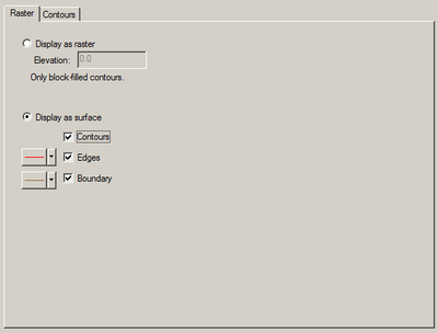
The raster display options are accessed by clicking on the Raster Options item or tab in the Display Options dialog. The default options vary between applications, and the options may be changed, saved, and restored within the project.
The following table describes the raster display options.
| Display Option | Description |
|---|---|
| Image Display | Select the "Display as raster" radio button to display the raster as a flat image rather than as a surface with elevation changes. Contour options are applied to form the image with block color fill. |
| Image Elevation | The raster image is drawn at an elevation of 0.0 by default. Change the "Elevation:" value to draw it at a different elevation. |
| Surface Display | Select the "Display as surface" radio button to display the raster as a height varying surface rather than as a flat image. Enable either Contours, Edges, or Boundary to see that type of surface or nothing will be shown. |
| Surface Contour | Select the "Contours" check box to apply contour options to the surface with contour lines and/or smooth color fill. |
| Surface Edges | Select the "Edges" check box to display the polygonal edges between height samples in the surface. The control to the left sets line color and either enables line dashes or species line width for the edges. This is typically the slowest surface to render. |
| Surface Boundary | Select the "Boundary" check box to display only those polygonal edges between height samples on the perimeter of the surface. The control to the left sets line color and either enables line dashes or species line width for the boundary. This is typically the fastest surface to render. |
