HY8:Energy Dissipators: Difference between revisions
From XMS Wiki
Jump to navigationJump to search
No edit summary |
m (moved WMS:HY-8 Energy Dissipators to HY-8:Energy Dissipators) |
(No difference)
| |
Revision as of 20:07, 9 January 2013
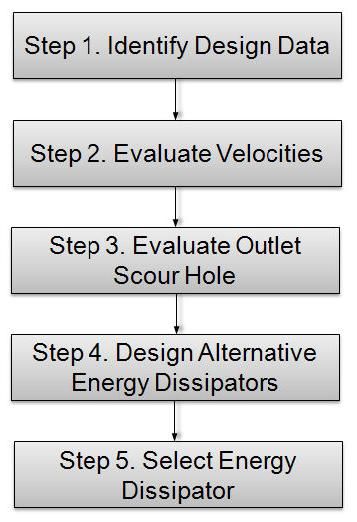
Hydraulic Engineering Circular No. 14 (HEC-14) describes several energy dissipating structures that can be used with culverts. HEC-14 describes procedures that can be used to compute scour hole sizes and design internal and external dissipators. It outlines the following steps that can be used when designing a culvert:
HEC-14 also describes the energy dissipators and their limitations as follows:
| Chapter | Dissipator Type | Froude Number[1] (Fr) | Allowable Debris[2] | Tailwater (TW) | ||
|---|---|---|---|---|---|---|
| Silt/Sand | Boulders | Floating | ||||
| 4 | Flow transitions | na | H | H | H | Desirable |
| 5 | Scour hole | na | H | H | H | Desirable |
| 6 | Hydraulic jump | > 1 | H | H | H | Required |
| 7 | Tumbling flow[3] | > 1 | M | L | L | Not needed |
| 7 | Increased resistance[4] | na | M | L | L | Not needed |
| 7 | USSBR Type IX baffled apron | < 1 | M | L | L | Not needed |
| 7 | Broken-back culvert | > 1 | M | L | L | Desirable |
| 7 | Outlet weir | 2 to 7 | M | L | M | Not needed |
| 7 | Outlet drop/weir | 3.5 to 6 | M | L | M | Not needed |
| 8 | USBR Type II stilling basin | 4.5 to 17 | M | L | M | Required |
| 8 | USBR Type IV stilling basin | 2.5 to 4.5 | M | L | M | Required |
| 8 | SAF stilling basin | 1.7 to 17 | M | L | M | Required |
| 9 | CSU rigid boundary basin | < 3 | M | L | M | Not needed |
| 9 | Contra Costa basin | < 3 | H | M | M | < 0.5D |
| 9 | Hook basin | 1.8 to 3 | H | M | M | Not needed |
| 9 | USBR Type VI impact basin[5] | na | M | L | L | Desirable |
| 10 | Riprap basin | < 3 | H | H | H | Not needed |
| 10 | Riprap apron[6] | na | M | L | L | Desirable |
| 11 | Straight drop structure[7] | < 1 | H | L | M | Required |
| 11 | Box inlet drop structure[8] | < 1 | H | L | M | Required |
| 12 | USACE stilling well | na | M | L | N | Desirable |
- ^ At release point from culvert or channel
- ^ Debris notes: N = none, L = low, M = moderate, H = heavy
- ^ Bed slope must be in the range 4% < So < 25%
- ^ Check headwater for outlet control
- ^ Discharge, Q < 11 m3/s (400 ft3/s) and Velocity, V < 15 m/s (50 ft/s)
- ^ Culvert rise less than or equal to 1500 mm (60 in)
- ^ Drop < 4.6 m (15 ft)
- ^ Drop < 3.7 m (12 ft)
- na = not applicable.
