HY8:Hydraulic Jump Calculations: Difference between revisions
| Line 679: | Line 679: | ||
== Hydraulic Jump Types == | == Hydraulic Jump Types == | ||
In HY-8, hydraulic jumps are divided into 3 different types: A, B, and C (See Figure 3). Type A jumps occur on a flat slope, and this condition often occurs at the downstream section of a [[ | In HY-8, hydraulic jumps are divided into 3 different types: A, B, and C (See Figure 3). Type A jumps occur on a flat slope, and this condition often occurs at the downstream section of a [[HY-8:Broken Back Culverts|broken back culvert]] if a hydraulic jump did not occur in the steep section of the culvert. Type B jumps only occur in [[WMS:HY-8 Broken Back Culverts|broken back culverts]] where the jump starts in the steep section of the culvert but finishes in the downstream section of the culvert. Type C jumps could occur in any sloped culverts. | ||
[[Image:HydraulicJumpTypes.png|650px]] | [[Image:HydraulicJumpTypes.png|650px]] | ||
Revision as of 19:45, 9 January 2013
Determining if a Hydraulic Jump Exists and its Location
A hydraulic jump is created in a rapidly varied flow situation where supercritical flow rapidly becomes subcritical flow. As the flow changes, energy is lost to turbulence. However, momentum is conserved across the jump. The two depths of flow just prior to and after a hydraulic jump are called sequent depths.
To determine if a hydraulic jump exists, HY-8 determines the supercritical and subcritical water surface profiles that form within the culvert using a direct step profile computation. At each location along the two profiles, HY-8 computes the sequent depths of the supercritical profile and compares these sequent depths to the subcritical profile’s computed depth.
While HY-8 computes the supercritical profile, a hydraulic jump forms if either of the following two conditions occurs: (1) the sequent depth profile intersects the subcritical profile, or (2) the Froude number is reduced to approximately 1.7 in a decelerating flow environment (M3, S3, H3, or A3 flow) (See the section in FHWA's HEC-14 on broken back culverts, 7.4).
If the outlet is submerged, HY-8 uses the energy equation to determine the hydraulic grade line. Once the hydraulic grade line falls below the crown of the culvert, HY-8 uses the direct step method to determine the remainder of the profile.
The equations used to determine the sequent depth vary by shape and are detailed in Nathan Lowe’s thesis (Lowe, 2008). Sequent Depths are not adjusted for slope or hydraulic jump type (see Hydraulic Jump Types).
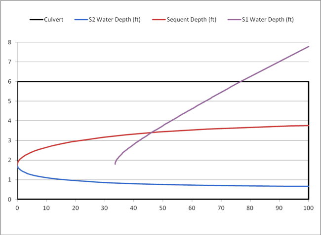
An example of a profile set and sequent depth calculations from a box culvert is given in Table 1 and plotted in Figure 1. The subcritical depth is shown extending above the crown of the culvert to show the hydraulic grade line for comparison purposes. Once HY-8 concludes the hydraulic jump calculations, the flow profile is modified to be contained within the culvert barrel.
Table 1: Parameters of culvert used for example
| Parameter | Value | Units |
|---|---|---|
|
Culvert Shape |
Box |
|
|
Rise: |
6.0 |
ft |
|
Span: |
6.0 |
ft |
|
Length: |
100.0 |
ft |
|
Flow: |
80.0 |
cfs |
Table 2: HY-8 Water Surface Profile and Sequent Depth Calculations
| Computation Direction: Upstream to Downstream | ||
|---|---|---|
| Location (ft) | S2 Water Depth (ft) | Sequent Depth (ft) |
|
0 |
1.767423128 |
1.767423128 |
|
0.029316423 |
1.717423128 |
1.818384336 |
|
0.121221217 |
1.667423128 |
1.871344458 |
|
0.284143628 |
1.617423128 |
1.926427128 |
|
0.528025114 |
1.567423128 |
1.983769228 |
|
0.86466911 |
1.517423128 |
2.043522893 |
|
1.308192917 |
1.467423128 |
2.105857905 |
|
1.87561876 |
1.417423128 |
2.17096453 |
|
2.587657601 |
1.367423128 |
2.239056945 |
|
3.469764745 |
1.317423128 |
2.310377355 |
|
4.553586554 |
1.267423128 |
2.385201009 |
|
5.878983069 |
1.217423128 |
2.463842333 |
|
7.496921363 |
1.167423128 |
2.546662495 |
|
9.473726216 |
1.117423128 |
2.634078814 |
|
11.89752361 |
1.067423128 |
2.726576563 |
|
14.88838 |
1.017423128 |
2.824723925 |
|
18.61499626 |
0.967423128 |
2.929191151 |
|
23.32377651 |
0.917423128 |
3.040775386 |
|
29.3931714 |
0.867423128 |
3.160433253 |
|
37.44519272 |
0.817423128 |
3.289324251 |
|
48.60550709 |
0.767423128 |
3.42886946 |
|
65.23610698 |
0.717423128 |
3.580832395 |
|
93.76009585 |
0.667423128 |
3.747432593 |
|
100 |
0.663122364 |
3.762533062 |
| Computation Direction: Downstream to Upstream | |
|---|---|
| Location (ft) | S1 Water Depth (ft) |
|
100 |
7.78884205 |
|
76.62538619 |
6 |
|
76.01536408 |
5.95 |
|
75.40596369 |
5.9 |
|
74.79697048 |
5.85 |
|
74.18839865 |
5.8 |
|
73.58026305 |
5.75 |
|
72.97257915 |
5.7 |
|
72.36536314 |
5.65 |
|
71.75863195 |
5.6 |
|
71.15240324 |
5.55 |
|
70.54669552 |
5.5 |
|
69.94152813 |
5.45 |
|
69.33692135 |
5.4 |
|
68.73289638 |
5.35 |
|
68.12947544 |
5.3 |
|
67.52668185 |
5.25 |
|
66.92454003 |
5.2 |
|
66.3230756 |
5.15 |
|
65.72231547 |
5.1 |
|
65.12228788 |
5.05 |
|
64.5230225 |
5 |
|
63.92455054 |
4.95 |
|
63.32690478 |
4.9 |
|
62.73011975 |
4.85 |
|
62.13423177 |
4.8 |
|
61.5392791 |
4.75 |
|
60.94530208 |
4.7 |
|
60.35234323 |
4.65 |
|
59.76044741 |
4.6 |
|
59.16966197 |
4.55 |
|
58.58003695 |
4.5 |
|
57.9916252 |
4.45 |
|
57.40448266 |
4.4 |
|
56.81866848 |
4.35 |
|
56.23424533 |
4.3 |
|
55.6512796 |
4.25 |
|
55.06984171 |
4.2 |
|
54.49000634 |
4.15 |
|
53.91185285 |
4.1 |
|
53.33546552 |
4.05 |
|
52.76093401 |
4 |
|
52.18835372 |
3.95 |
|
51.61782627 |
3.9 |
|
51.04946001 |
3.85 |
|
50.48337049 |
3.8 |
|
49.91968113 |
3.75 |
|
49.35852381 |
3.7 |
|
48.80003962 |
3.65 |
|
48.24437962 |
3.6 |
|
47.69170569 |
3.55 |
|
47.1421915 |
3.5 |
|
46.59602356 |
3.45 |
|
46.05340235 |
3.4 |
|
45.51454362 |
3.35 |
|
44.97967983 |
3.3 |
|
44.44906168 |
3.25 |
|
43.92295991 |
3.2 |
|
43.40166723 |
3.15 |
|
42.88550053 |
3.1 |
|
42.37480328 |
3.05 |
|
41.86994835 |
3 |
|
41.37134098 |
2.95 |
|
40.87942233 |
2.9 |
|
40.39467334 |
2.85 |
|
39.91761912 |
2.8 |
|
39.44883402 |
2.75 |
|
38.98894719 |
2.7 |
|
38.53864914 |
2.65 |
|
38.09869903 |
2.6 |
|
37.66993312 |
2.55 |
|
37.25327445 |
2.5 |
|
36.84974393 |
2.45 |
|
36.46047324 |
2.4 |
|
36.08671965 |
2.35 |
|
35.72988334 |
2.3 |
|
35.39152756 |
2.25 |
|
35.07340226 |
2.2 |
|
34.77747182 |
2.15 |
|
34.50594783 |
2.1 |
|
34.26132798 |
2.05 |
|
34.04644235 |
2 |
|
33.86450893 |
1.95 |
|
33.71920038 |
1.9 |
|
33.61472501 |
1.85 |
|
33.55592549 |
1.8 |
Figure 1: HY-8 Water Surface Profile and Sequent Depth Calculations
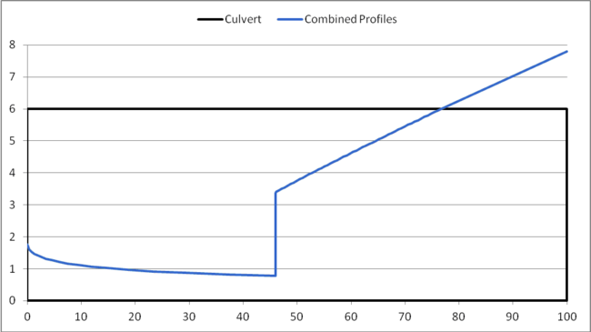
In Figure 1, the sequent depth shown by the red line crosses the S1 water depth shown by the purple line. The point of intersection is where a hydraulic jump occurs and is located at approximately 46’ downstream of the inlet of the culvert. HY-8 creates a combined water surface profile from the two profiles. If you assume that the length of the hydraulic jump is zero, the jump would be a vertical line. An example of a water surface profile for a hydraulic jump assuming zero jump length is shown in Figure 2.
Figure 2: Water Surface Profile Assuming a Jump Length of Zero
Once HY-8 determines that a jump occurs and the jump's location, HY-8 determines the length of the jump and applies that length to the profile. Before determining the length, however, HY-8 must first determine the type of hydraulic jump so the appropriate equation can be used for computing the length.
Hydraulic Jump Types
In HY-8, hydraulic jumps are divided into 3 different types: A, B, and C (See Figure 3). Type A jumps occur on a flat slope, and this condition often occurs at the downstream section of a broken back culvert if a hydraulic jump did not occur in the steep section of the culvert. Type B jumps only occur in broken back culverts where the jump starts in the steep section of the culvert but finishes in the downstream section of the culvert. Type C jumps could occur in any sloped culverts.
Figure 3: Hydraulic Jump Types used in HY-8
Determining the Length of a Hydraulic Jump
HY-8 uses equations determined by Bradley and Peterka (1957) and Hager (1992) as shown in the following table. Complete information about the lengths of hydraulic jumps does not exist in the literature. These portions of the table, where equations representing the hydraulic jump length are not available, are denoted with a "-". In instances where an equation has not been determined, an explanation of how HY-8 computes the length is shown.
Table 3: HY-8 Hydraulic Jump Length Equations
| Culvert Shape | Flat Slope (Type A) | Sloped Culvert (Type C) | Jump Over Slope Break (Type B) |
|---|---|---|---|
|
Circular |
- (Use box equation) |
- (Use box equation) | |
|
Box |
First solve for Fr1t Then, if Fr1 > Fr1t Lj = Lj* Otherwise, if Fr1 <= Fr1t where: E = (h2 - z1) / h2 | ||
|
Ellipse |
Use longer of circular and box equations |
- (Use box equation) |
- (Use box equation) |
|
Pipe Arch |
Use longer of circular and box equations |
- (Use box equation) |
- (Use box equation) |
|
User Defined/Other |
Use longer of circular and box equations |
- (Use box equation) |
- (Use box equation) |
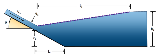
In the above table, you can see that the literature is incomplete for the jump lengths of several of the shapes supported in HY-8. Further research is required for a more accurate analysis. The following variables are used in the above table and are shown in Figure 4:
Lj* = Length of the hydraulic jump on a flat slope (ft or m)
y1 = Sequent depth at the upstream end of the hydraulic jump (ft or m)
y2 = Sequent depth at the downstream end of the hydraulic jump (ft or m)
Fr1 = Froude number at the upstream end of the hydraulic jump
θ = Channel angle of repose (in radians, = Arctan(channel slope))
Lj = Length of the hydraulic jump on a sloping channel (ft or m)
z1 = Distance from the invert of the flat part of the channel to the channel invert at the beginning of the jump (ft or m)
h2 = Depth of water on a flat slope after the jump (ft or m)
Figure 4: Variable definitions used in hydraulic jump length computations
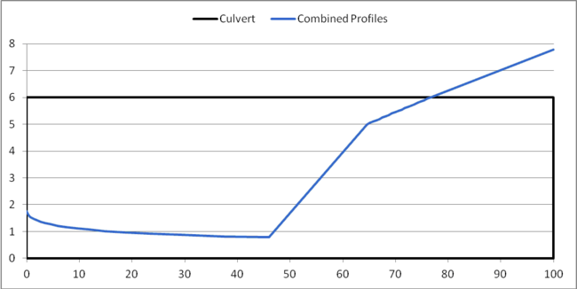
HY-8 determines the length of the jump and modifies the profile to an angled transition to the subcritical flow rather than a vertical transition. The beginning of the jump is assumed to be the location previously determined as the jump location. The end of the jump is the beginning of the jump plus the jump length. If the end of the jump is outside of the culvert, the jump is assumed to be swept out. This may or may not happen, but is considered to be conservative. This assumption means HY-8 reports less hydraulic jumps than may actually occur. Example hydraulic jump length calculations are shown in Table 4. The profile showing the hydraulic jump with the jump length applied is shown in Figure 5.
Table 4: Sample Hydraulic Jump Length Calculations
| Parameter | Value | Units |
|---|---|---|
|
Culvert Shape |
Box |
|
|
Froude Number 1: |
3.4229 |
|
|
Depth 1: |
0.7778 |
ft |
|
Length of Jump: |
18.77 |
ft |
|
Station 1: |
46.0 |
ft |
|
Station 2: |
64.8 |
ft |
Figure 5: Water Profile with Hydraulic Jump with Calculated Jump Length
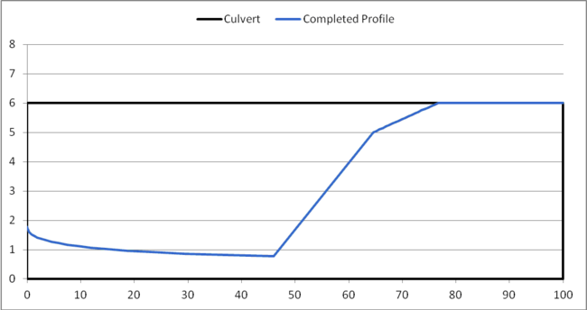
When HY-8 finishes computing the hydraulic jump length, and has applied it to the profile, HY-8 trims the profile to stay within the culvert barrel. The completed profile is shown in Figure 6.
Figure 6: Completed Water Surface Profile
References
Lowe, N. J. (2008). THEORETICAL DETERMINATION OF SUBCRITICAL SEQUENT DEPTHS FOR COMPLETE AND INCOMPLETE HYDRAULIC JUMPS IN CLOSED CONDUITS OF ANY SHAPE. Provo, Utah: Brigham Young University.
Bradley, J.N. and Peterka, A.J., The hydraulic design of stilling basins: hydraulic jumps on a horizontal apron (Basin I), Journal of the Hydraulics Division, ASCE, 83 (HY5), pp. 1401 (1-24), 1957.
Hager, W.H. Energy Dissipators and Hydraulic Jump. Kluwer Academic Publishers, Dordrecht, Netherlands, 1992.
