HY8:Polynomial Coefficients: Difference between revisions
No edit summary |
No edit summary |
||
| Line 1: | Line 1: | ||
For circular, box, elliptical, and | For circular, box, elliptical, pipe arch, and concrete open-bottom arch (commonly called CON/SPAN) culverts, polynomial coefficients, found in Tables 1-5, are utilized in the inlet control headwater computations. Tables 6-10 show the HW/D points A(1) through A(10) for interpolation. Each row of coefficients represents different entrance conditions for different culvert shapes. | ||
Table 1. Polynomial Coefficients - Circular | == Table 1. Polynomial Coefficients - Circular == | ||
[[Image:HY8Poly_Table_1.JPG]] | [[Image:HY8Poly_Table_1.JPG]] | ||
| Line 13: | Line 13: | ||
1-10: Hydraulic Computer Program (HY) 1, FHWA, 1969, page 18 | 1-10: Hydraulic Computer Program (HY) 1, FHWA, 1969, page 18 | ||
Table 2. Polynomial Coefficients - Box | == Table 2. Polynomial Coefficients - Box == | ||
[[Image:HY8Poly_Table_2.JPG]] | [[Image:HY8Poly_Table_2.JPG]] | ||
| Line 33: | Line 33: | ||
Table 3. Polynomial Coefficients - Ellipse | == Table 3. Polynomial Coefficients - Ellipse == | ||
[[Image:HY8Poly_Table_3.JPG]] | [[Image:HY8Poly_Table_3.JPG]] | ||
| Line 47: | Line 47: | ||
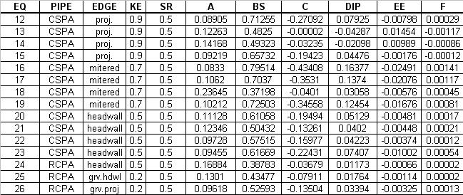
Table 4. Polynomial Coefficients - Pipe Arch | == Table 4. Polynomial Coefficients - Pipe Arch == | ||
[[Image:HY8Polynomial_PipeArch.JPG]] | [[Image:HY8Polynomial_PipeArch.JPG]] | ||
| Line 59: | Line 59: | ||
12,16,20: Hydraulic Computer Program (HY) 2, FHWA, 1969, page 17 | 12,16,20: Hydraulic Computer Program (HY) 2, FHWA, 1969, page 17 | ||
Table | == Table 5. Polynomial Coefficients - Concrete Open-Bottom Arch == | ||
{| class="wikitable" | {| class="wikitable" | ||
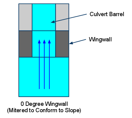
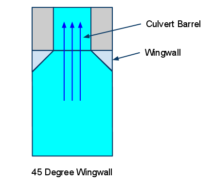
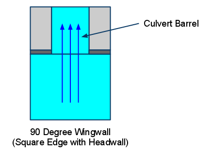
! Span:Rise Ratio !! Wingwall Angle (Inlet Edge Condition) !! KE !! SR !! A !! B !! C !! D !! E !! F !! Diagram/Notes | ! Span:Rise Ratio !! Wingwall Angle (Inlet Edge Condition) !! KE !! SR !! A !! B !! C !! D !! E !! F !! Diagram/Notes | ||
| Line 243: | Line 213: | ||
* Thiele, Elizabeth A. Culvert Hydraulics: Comparison of Current Computer Models. (pp. 121-126), Brigham Young University Master's Thesis (2007). | * Thiele, Elizabeth A. Culvert Hydraulics: Comparison of Current Computer Models. (pp. 121-126), Brigham Young University Master's Thesis (2007). | ||
* Chase, Don. Hydraulic Characteristics of CON/SPAN Bridge Systems. Submitted Study and Report (1999) | * Chase, Don. Hydraulic Characteristics of CON/SPAN Bridge Systems. Submitted Study and Report (1999) | ||
== Table 6. Arch HW/D Values. == | |||
[[Image:HY8Arch%20Table.JPG]] | |||
== Table 7. High Profile Arch HW/D Values. == | |||
[[Image:HY8Arch%20High%20Profile.JPG]] | |||
== Table 8. Low Profile Arch HW/D Values. == | |||
[[Image:HY8Arch%20Low%20Profile%20Table.JPG]] | |||
== Table 9. Metal Box HW/D Values. == | |||
[[Image:HY8Metal%20Box.JPG]] | |||
== Table 10. User Defined HW/D Values. == | |||
[[Image:HY8User%20Defined%20Table.JPG]] | |||
Revision as of 23:19, 16 June 2011
For circular, box, elliptical, pipe arch, and concrete open-bottom arch (commonly called CON/SPAN) culverts, polynomial coefficients, found in Tables 1-5, are utilized in the inlet control headwater computations. Tables 6-10 show the HW/D points A(1) through A(10) for interpolation. Each row of coefficients represents different entrance conditions for different culvert shapes.
Table 1. Polynomial Coefficients - Circular
EQ #'s: REFERENCE
1-9 : Calculator Design Series (CDS) 3 for TI-59, FHWA, 198O, page 60
1-10: Hydraulic Computer Program (HY) 1, FHWA, 1969, page 18
Table 2. Polynomial Coefficients - Box
EQ #'s: REFERENCE
1-6: Hydraulic Computer Program (HY) 6, FHWA, 1969, subroutine BEQUA
1,4,5: Hydraulic Computer Program (HY) 3, FHWA, 1969, page 16
1,3,4,6: Calculator Design Series (CDS) 3 for TI-59, FHWA, 198O, page 16
Table 3. Polynomial Coefficients - Ellipse
EQ #'s: REFERENCE
27-30: Calculator Design Series (CDS) 4 for TI-59, FHWA, 1982, page 20
31-33: Calculator Design Series (CDS) 4 for TI-59, FHWA, 1982, page 22
Table 4. Polynomial Coefficients - Pipe Arch
EQ #'s: REFERENCE
12-23: Calculator Design Series (CDS) 4 for TI-59, FHWA, 1982, page 17
24-26: Calculator Design Series (CDS) 4 for TI-59, FHWA, 1982, page 24
12,16,20: Hydraulic Computer Program (HY) 2, FHWA, 1969, page 17
Table 5. Polynomial Coefficients - Concrete Open-Bottom Arch
| Span:Rise Ratio | Wingwall Angle (Inlet Edge Condition) | KE | SR | A | B | C | D | E | F | Diagram/Notes |
|---|---|---|---|---|---|---|---|---|---|---|
| 2:1 |
0 Degrees (Mitered to Conform to Slope) |
0.7 |
0.5 |
0.0356 |
0.5701 |
-0.162 |
0.0322 |
-0.0023 |
0.00006 |
2:1 Coefficients are used if the span:rise ratio is less than or equal to 3:1. |
| 2:1 |
45 Degrees (45-degree Wingwall) |
0.2 if beveled, use 0.5 if not beveled (square edge) |
0.5 |
0.0393 |
0.5828 |
-0.1518 |
0.0284 |
-0.002 |
0.00005 |
2:1 Coefficients are used if the span:rise ratio is less than or equal to 3:1. |
| 2:1 |
90 Degrees (Square Edge with Headwall) |
0.5 |
0.5 |
0.0459 |
0.5762 |
-0.1436 |
0.0269 |
-0.0019 |
0.00005 |
2:1 Coefficients are used if the span:rise ratio is less than or equal to 3:1. |
| 4:1 |
0 Degrees (Mitered to Conform to Slope) |
0.7 |
0.5 |
0.0309 |
0.5211 |
-0.1258 |
0.0207 |
-0.0013 |
0.00003 |
4:1 coefficients are used if the span:rise ratio is greater than 3:1 |
| 4:1 |
45 Degrees (45-degree Wingwall) |
0.2 if beveled, use 0.5 if not beveled (square edge) |
0.5 |
0.0318 |
0.5446 |
-0.1467 |
0.0273 |
-0.0019 |
0.00005 |
4:1 coefficients are used if the span:rise ratio is greater than 3:1 |
| 4:1 |
90 Degrees (Square Edge with Headwall) |
0.5 |
0.5 |
0.0283 |
0.5739 |
-0.1584 |
0.0292 |
-0.002 |
0.00005 |
4:1 coefficients are used if the span:rise ratio is greater than 3:1 |
References for Concrete Open-bottom Arch polynomial coefficients:
- Thiele, Elizabeth A. Culvert Hydraulics: Comparison of Current Computer Models. (pp. 121-126), Brigham Young University Master's Thesis (2007).
- Chase, Don. Hydraulic Characteristics of CON/SPAN Bridge Systems. Submitted Study and Report (1999)
Table 6. Arch HW/D Values.
Table 7. High Profile Arch HW/D Values.
Table 8. Low Profile Arch HW/D Values.
Table 9. Metal Box HW/D Values.
Table 10. User Defined HW/D Values.


