HY8:Polynomial Coefficients: Difference between revisions
| Line 941: | Line 941: | ||
0.0001097816 | 0.0001097816 | ||
| | | | ||
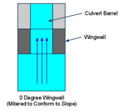
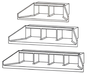
[[File:0DegreeWingwallConspanCulvertDiagram.png| | [[File:0DegreeWingwallConspanCulvertDiagram.png|250px]] | ||
2:1 Coefficients are used if the span:rise ratio is less than or equal to 3:1. | 2:1 Coefficients are used if the span:rise ratio is less than or equal to 3:1. | ||
| Line 965: | Line 965: | ||
0.0000796275 | 0.0000796275 | ||
| | | | ||
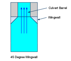
[[File:45DegreeWingwallConspanCulvertDiagram.png| | [[File:45DegreeWingwallConspanCulvertDiagram.png|250px]] | ||
2:1 Coefficients are used if the span:rise ratio is less than or equal to 3:1. | 2:1 Coefficients are used if the span:rise ratio is less than or equal to 3:1. | ||
| Line 989: | Line 989: | ||
0.0000632552 | 0.0000632552 | ||
| | | | ||
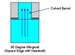
[[File:90DegreeWingwallConspanCulvertDiagram.png| | [[File:90DegreeWingwallConspanCulvertDiagram.png|250px]] | ||
2:1 Coefficients are used if the span:rise ratio is less than or equal to 3:1. | 2:1 Coefficients are used if the span:rise ratio is less than or equal to 3:1. | ||
| Line 1,013: | Line 1,013: | ||
0.0000404218 | 0.0000404218 | ||
| | | | ||
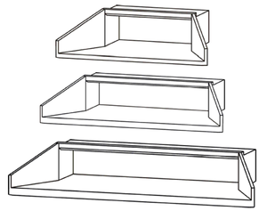
[[File:0DegreeWingwallConspanCulvertDiagram.png| | [[File:0DegreeWingwallConspanCulvertDiagram.png|250px]] | ||
4:1 coefficients are used if the span:rise ratio is greater than 3:1 | 4:1 coefficients are used if the span:rise ratio is greater than 3:1 | ||
| Line 1,037: | Line 1,037: | ||
0.0000704011 | 0.0000704011 | ||
| | | | ||
[[File:45DegreeWingwallConspanCulvertDiagram.png| | [[File:45DegreeWingwallConspanCulvertDiagram.png|250px]] | ||
4:1 coefficients are used if the span:rise ratio is greater than 3:1 | 4:1 coefficients are used if the span:rise ratio is greater than 3:1 | ||
| Line 1,061: | Line 1,061: | ||
0.0000668323 | 0.0000668323 | ||
| | | | ||
[[File:90DegreeWingwallConspanCulvertDiagram.png| | [[File:90DegreeWingwallConspanCulvertDiagram.png|250px]] | ||
4:1 coefficients are used if the span:rise ratio is greater than 3:1 | 4:1 coefficients are used if the span:rise ratio is greater than 3:1 | ||
Revision as of 15:40, 7 October 2011
Overview
For circular, box, elliptical, pipe arch, concrete open-bottom arch (commonly called CON/SPAN), and South Dakota Concrete Box culverts, polynomial coefficients, found in Tables 1-6, are utilized in the inlet control headwater computations. Table 7 shows the HW/D points A(1) through A(10) for interpolation. Each row of coefficients represents different inlet configurations for different culvert shapes.
Note About Coefficient Changes in HY-8 7.3 and Higher
In HY-8 7.3 and later versions of HY-8, several significant changes were made to the coefficients used in HY-8. A summary of the changes to the HY-8 coefficients in this version follows:
Changes to Shapes Using Polynomial Coefficients
Changed the slope correction coefficient, SR, used for all the mitered inlet configurations to the recommended -0.7
Changes to Box Culverts
Changed the 1.5:1 Bevel Wingwall inlet configuration from HY-8 Equation 6 to equation 2. For HY-8 Equations 2, 3, and 6, added 0.01 to the "A" Coefficient in the shape database to account for the fact that the equations were derived using a 2% slope (a 2% slope was used to derive the polynomial equations, meaning 0.5(0.02) was subtracted from each of the polynomial curves and needed to be added back into the equations before correcting for slopes).
Changes to Shapes using A(1) to A(10) Interpolation Coefficients
Added the slope correction term SR*Slope to the interpolation equations in the code and added 0.01 to the interpolation coefficients for thin, square, and bevel inlets. Subtracted 0.01 for the mitered inlet. Added the SR coefficients (All = 0.5 except for mitered which = -0.7) to the coefficient database and the documentation on this page.
Table 1. Polynomial Coefficients - Circular
| HY-8 Equation | Inlet Configuration | KE | SR | A | BS | C | DIP | EE | F |
|---|---|---|---|---|---|---|---|---|---|
|
1 |
Thin Edge Projecting |
0.9 |
0.5 |
0.187321 |
0.56771 |
-0.156544 |
0.0447052 |
-0.00343602 |
8.96610E-05 |
|
2 |
Mitered to Conform to Slope |
0.7 |
-0.7 |
0.107137 |
0.757789 |
-0.361462 |
0.1233932 |
-0.01606422 |
0.00076739 |
|
3 |
Square Edge with Headwall (Steel/Aluminum/Corrugated PE) |
0.5 |
0.5 |
0.167433 |
0.538595 |
-0.149374 |
0.0391543 |
-0.00343974 |
0.000115882 |
|
4 |
Grooved End Projecting |
0.2 |
0.5 |
0.108786 |
0.662381 |
-0.233801 |
0.0579585 |
-0.0055789 |
0.000205052 |
|
5 |
Grooved End in Headwall |
0.2 |
0.5 |
0.114099 |
0.653562 |
-0.233615 |
0.0597723 |
-0.00616338 |
0.000242832 |
|
6 |
Beveled Edge (1:1) |
0.2 |
0.5 |
0.063343 |
0.766512 |
-0.316097 |
0.0876701 |
-0.009836951 |
0.00041676 |
|
7 |
Beveled Edge (1.5:1) |
0.2 |
0.5 |
0.08173 |
0.698353 |
-0.253683 |
0.065125 |
-0.0071975 |
0.000312451 |
|
8 |
sq. proj. |
0.2 |
0.5 |
0.167287 |
0.558766 |
-0.159813 |
0.0420069 |
-0.00369252 |
0.000125169 |
|
9 |
Square Edge with Headwall (Concrete/PVC/HDPE) |
0.5 |
0.5 |
0.087483 |
0.706578 |
-0.253295 |
0.0667001 |
-0.00661651 |
0.000250619 |
|
10 |
end sect. |
0.4 |
0.5 |
0.120659 |
0.630768 |
-0.218423 |
0.0591815 |
-0.00599169 |
0.000229287 |
EQ #'s: REFERENCE
1-9 : Calculator Design Series (CDS) 3 for TI-59, FHWA, 198O, page 60
1-10: Hydraulic Computer Program (HY) 1, FHWA, 1969, page 18
Table 2. Polynomial Coefficients - Box
| HY-8 Equation | Inlet Configuration | KE | SR | A | BS | C | DIP | EE | F |
|---|---|---|---|---|---|---|---|---|---|
|
1 |
Square Edge (90 degree) Headwall, Square Edge (90 & 15 degree flare) Wingwall |
0.5 |
0.5 |
0.122117 |
0.505435 |
-0.10856 |
0.0207809 |
-0.00136757 |
0.00003456 |
|
2 |
1.5:1 Bevel (90 degree) Headwall, 1.5:1 Bevel (19-34 degree flare) Wingwall |
0.2 |
0.5 |
0.1067588 |
0.4551575 |
-0.08128951 |
0.01215577 |
-0.00067794 |
0.0000148 |
|
3 |
1:1 Bevel Headwall |
0.2 |
0.5 |
0.1666086 |
0.3989353 |
-0.06403921 |
0.01120135 |
-0.0006449 |
0.000014566 |
|
4 |
Square Edge (30-75 degree flare) Wingwall |
0.4 |
0.5 |
0.0724927 |
0.507087 |
-0.117474 |
0.0221702 |
-0.00148958 |
0.000038 |
|
5 |
Square Edge (0 degree flare) Wingwall |
0.7 |
0.5 |
0.144133 |
0.461363 |
-0.0921507 |
0.0200028 |
-0.00136449 |
0.0000358 |
|
6 |
1:1 Bevel (45 degree flare) Wingwall |
0.2 |
0.5 |
0.0995633 |
0.4412465 |
-0.07434981 |
0.01273183 |
-0.0007588 |
0.00001774 |
EQ #'s: REFERENCE
1-6: Hydraulic Computer Program (HY) 6, FHWA, 1969, subroutine BEQUA
1,4,5: Hydraulic Computer Program (HY) 3, FHWA, 1969, page 16
1,3,4,6: Calculator Design Series (CDS) 3 for TI-59, FHWA, 1980, page 16
Table 3. Polynomial Coefficients - Ellipse
| HY-8 Equation | PIPE | Inlet Configuration | KE | SR | A | BS | C | DIP | EE | F |
|---|---|---|---|---|---|---|---|---|---|---|
|
27 |
CSPE |
headwall |
0.5 |
0.5 |
0.01267 |
0.79435 |
-0.2944 |
0.07114 |
-0.00612 |
0.00015 |
|
28 |
CSPE |
mitered |
0.7 |
-0.7 |
-0.14029 |
1.437 |
-0.92636 |
0.32502 |
-0.04865 |
0.0027 |
|
29 |
CSPE |
bevel |
0.3 |
0.5 |
-0.00321 |
0.92178 |
-0.43903 |
0.12551 |
-0.01553 |
0.00073 |
|
30 |
CSPE |
thin |
0.9 |
0.5 |
0.0851 |
0.70623 |
-0.18025 |
0.01963 |
0.00402 |
-0.00052 |
|
31 |
RCPE |
square |
0.5 |
0.5 |
0.13432 |
0.55951 |
-0.1578 |
0.03967 |
-0.0034 |
0.00011 |
|
32 |
RCPE |
grv. hdwl |
0.2 |
0.5 |
0.15067 |
0.50311 |
-0.12068 |
0.02566 |
-0.00189 |
0.00005 |
|
33 |
RCPE |
grv. proj |
0.2 |
0.5 |
-0.03817 |
0.84684 |
-0.32139 |
0.0755 |
-0.00729 |
0.00027 |
EQ #'s: REFERENCE
27-30: Calculator Design Series (CDS) 4 for TI-59, FHWA, 1982, page 20
31-33: Calculator Design Series (CDS) 4 for TI-59, FHWA, 1982, page 22
Table 4. Polynomial Coefficients - Pipe Arch
| HY-8 Equation | PIPE | Inlet Configuration | KE | SR | A | BS | C | DIP | EE | F |
|---|---|---|---|---|---|---|---|---|---|---|
|
12 |
CSPA |
proj. |
0.9 |
0.5 |
0.08905 |
0.71255 |
-0.27092 |
0.07925 |
-0.00798 |
0.00029 |
|
13 |
CSPA |
proj. |
0.9 |
0.5 |
0.12263 |
0.4825 |
-0.00002 |
-0.04287 |
0.01454 |
-0.00117 |
|
14 |
CSPA |
proj. |
0.9 |
0.5 |
0.14168 |
0.49323 |
-0.03235 |
-0.02098 |
0.00989 |
-0.00086 |
|
15 |
CSPA |
proj. |
0.9 |
0.5 |
0.09219 |
0.65732 |
-0.19423 |
0.04476 |
-0.00176 |
-0.00012 |
|
16 |
CSPA |
mitered |
0.7 |
-0.7 |
0.0833 |
0.79514 |
-0.43408 |
0.16377 |
-0.02491 |
0.00141 |
|
17 |
CSPA |
mitered |
0.7 |
-0.7 |
0.1062 |
0.7037 |
-0.3531 |
0.1374 |
-0.02076 |
0.00117 |
|
18 |
CSPA |
mitered |
0.7 |
-0.7 |
0.23645 |
0.37198 |
-0.0401 |
0.03058 |
-0.00576 |
0.00045 |
|
19 |
CSPA |
mitered |
0.7 |
-0.7 |
0.10212 |
0.72503 |
-0.34558 |
0.12454 |
-0.01676 |
0.00081 |
|
20 |
CSPA |
headwall |
0.5 |
0.5 |
0.11128 |
0.61058 |
-0.19494 |
0.05129 |
-0.00481 |
0.00017 |
|
21 |
CSPA |
headwall |
0.5 |
0.5 |
0.12346 |
0.50432 |
-0.13261 |
0.0402 |
-0.00448 |
0.00021 |
|
22 |
CSPA |
headwall |
0.5 |
0.5 |
0.09728 |
0.57515 |
-0.15977 |
0.04223 |
-0.00374 |
0.00012 |
|
23 |
CSPA |
headwall |
0.5 |
0.5 |
0.09455 |
0.61669 |
-0.22431 |
0.07407 |
-0.01002 |
0.00054 |
|
24 |
RCPA |
headwall |
0.5 |
0.5 |
0.16884 |
0.38783 |
-0.03679 |
0.01173 |
-0.00066 |
0.00002 |
|
25 |
RCPA |
grv. hdwl |
0.2 |
0.5 |
0.1301 |
0.43477 |
-0.07911 |
0.01764 |
-0.00114 |
0.00002 |
|
26 |
RCPA |
grv. proj |
0.2 |
0.5 |
0.09618 |
0.52593 |
-0.13504 |
0.03394 |
-0.00325 |
0.00013 |
EQ #'s: REFERENCE
12-23: Calculator Design Series (CDS) 4 for TI-59, FHWA, 1982, page 17
24-26: Calculator Design Series (CDS) 4 for TI-59, FHWA, 1982, page 24
12,16,20: Hydraulic Computer Program (HY) 2, FHWA, 1969, page 17
Table 5. Polynomial Coefficients - Concrete Open-Bottom Arch
| Span:Rise Ratio | Wingwall Angle (Inlet Configuration) | KE | SR | A | BS | C | DIP | EE | F | Diagram/Notes |
|---|---|---|---|---|---|---|---|---|---|---|
| 2:1 |
0 Degrees (Mitered to Conform to Slope) |
0.7 |
0.0 |
0.0389106557 |
0.6044131889 |
-0.1966160961 |
0.0425827445 |
-0.0035136880 |
0.0001097816 |
2:1 Coefficients are used if the span:rise ratio is less than or equal to 3:1. |
| 2:1 |
45 Degrees (45-degree Wingwall) |
0.5 |
0.0 |
0.0580199163 |
0.5826504262 |
-0.1654982156 |
0.0337114383 |
-0.0026437555 |
0.0000796275 |
2:1 Coefficients are used if the span:rise ratio is less than or equal to 3:1. |
| 2:1 |
90 Degrees (Square Edge with Headwall) |
0.5 |
0.0 |
0.0747688320 |
0.5517030198 |
-0.1403253664 |
0.0281511418 |
-0.0021405250 |
0.0000632552 |
2:1 Coefficients are used if the span:rise ratio is less than or equal to 3:1. |
| 4:1 |
0 Degrees (Mitered to Conform to Slope) |
0.7 |
0.0 |
0.0557401882 |
0.4998819105 |
-0.1249164198 |
0.0219465031 |
-0.0015177347 |
0.0000404218 |
4:1 coefficients are used if the span:rise ratio is greater than 3:1 |
| 4:1 |
45 Degrees (45-degree Wingwall) |
0.5 |
0.0 |
0.0465032346 |
0.5446293346 |
-0.1571341119 |
0.0312822438 |
-0.0024007467 |
0.0000704011 |
4:1 coefficients are used if the span:rise ratio is greater than 3:1 |
| 4:1 |
90 Degrees (Square Edge with Headwall) |
0.5 |
0.0 |
0.0401619369 |
0.5774418238 |
-0.1693724912 |
0.0328323405 |
-0.0024131276 |
0.0000668323 |
4:1 coefficients are used if the span:rise ratio is greater than 3:1 |
References for Concrete Open-bottom Arch polynomial coefficients:
- Thiele, Elizabeth A. Culvert Hydraulics: Comparison of Current Computer Models. (pp. 121-126), Brigham Young University Master's Thesis (2007).
- Chase, Don. Hydraulic Characteristics of CON/SPAN Bridge Systems. Submitted Study and Report (1999)
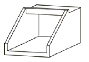
Table 6. Polynomial Coefficients - South Dakota Concrete Box
| Description | KE | SR | A | BS | C | DIP | EE | F | Diagram/Notes |
|---|---|---|---|---|---|---|---|---|---|
| Sketch 1: 30 degree-flared wingwalls; top edge beveled at 45 degrees |
0.5 |
0.5 |
0.0176998563 |
0.5354484847 |
-0.1197176702 |
0.0175902318 |
-0.0005722076 |
-0.0000080574 |
|
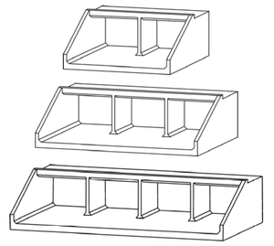
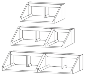
| Sketch 2: 30 degree-flared wingwalls; top edge beveled at 45 degrees; 2, 3, and 4 multiple barrels |
0.5 |
0.5 |
0.0506647261 |
0.5535393634 |
-0.1599374238 |
0.0339859269 |
-0.0027470036 |
0.0000851484 |
|
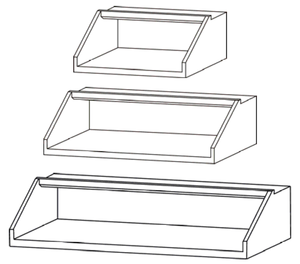
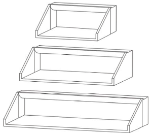
| Sketch 3: 30 degree-flared wingwalls; top edge beveled at 45 degrees; 2:1 to 4:1 span-to-rise ratio |
0.5 |
0.5 |
0.0518005829 |
0.5892384653 |
-0.1901266252 |
0.0412149379 |
-0.0034312198 |
0.0001083949 |
|
| Sketch 4: 30 degree-flared wingwalls; top edge beveled at 45 degrees; 15 degrees skewed headwall with multiple barrels |
0.5 |
0.5 |
0.2212801152 |
0.6022032341 |
-0.1672369732 |
0.0313391792 |
-0.0024440549 |
0.0000743575 |
|
| Sketch 5: 30 degree-flared wingwalls; top edge beveled at 45 degrees; 30 degrees to 45 degrees skewed headwall with multiple barrels |
0.5 |
0.5 |
0.2431604850 |
0.5407556631 |
-0.1267568901 |
0.0223638322 |
-0.0016523399 |
0.0000490932 |
|
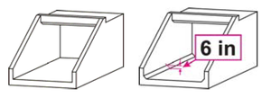
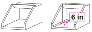
| Sketches 6 & 7: 0 degree-flared wingwalls (extended sides); square-edged at crown and 0 degree-flared wingwalls (extended sides); top edge beveled at 45 degrees; 0- and 6-inch corner fillets |
0.5 |
0.5 |
0.0493946080 |
0.7138391179 |
-0.2354755894 |
0.0473247331 |
-0.0036154348 |
0.0001033337 |
|
| Sketches 8 & 9: 0 degree-flared wingwalls (extended sides); top edge beveled at 45 degrees; 2, 3, and 4 multiple barrels and 0 degree-flared wingwalls (extended sides); top edge beveled at 45 degrees; 2:1 to 4:1 span-to-rise ratio |
0.5 |
0.5 |
0.1013668008 |
0.6600937637 |
-0.2133066786 |
0.0437022641 |
-0.0035224589 |
0.0001078198 |
|
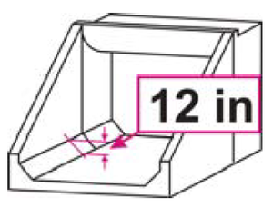
| Sketches 10 & 11: 0 degree-flared wingwalls (extended sides); crown rounded at 8-inch radius; 0- and 6-inch corner fillets and 0 degree-flared wingwalls (extended sides); crown rounded at 8-inch radius; 12-inch corner fillets |
0.5 |
0.5 |
0.0745605288 |
0.6533033536 |
-0.1899798824 |
0.0350021004 |
-0.0024571627 |
0.0000642284 |
|
| Sketch 12: 0 degree-flared wingwalls (extended sides); crown rounded at 8-inch radius; 12-inch corner fillets; 2, 3, and 4 multiple barrels |
0.5 |
0.5 |
0.1321993533 |
0.5024365440 |
-0.1073286526 |
0.0183092064 |
-0.0013702887 |
0.0000423592 |
|
| Sketch 13: 0 degree-flared wingwalls (extended sides); crown rounded at 8-inch radius; 12-inch corner fillets; 2:1 to 4:1 span-to-rise ratio. |
0.5 |
0.5 |
0.1212726739 |
0.6497418331 |
-0.1859782730 |
0.0336300433 |
-0.0024121680 |
0.0000655665 |
References for South Dakota Concrete Box polynomial coefficients:
- Thiele, Elizabeth A. Culvert Hydraulics: Comparison of Current Computer Models. (pp. 121-126), Brigham Young University Master's Thesis (2007).
- Effects of Inlet Geometry on Hydraulic Performance of Box Culverts (FHWA Publication No. FHWA-HRT-06-138, October 2006)
Table 7. User Defined, Open Bottom Arch, Low-Profile Arch, High-Profile Arch, and Metal Box HW/D Values.
| Q/A*D^.5 = | 0.5 | 1 | 2 | 3 | 4 | 5 | 6 | 7 | 8 | 9 | |||
|---|---|---|---|---|---|---|---|---|---|---|---|---|---|
| HY-8 Interpolation Coefficients | Inlet Configuration | KE | SR | A(1) | A(2) | A(3) | A(4) | A(5) | A(6) | A(7) | A(8) | A(9) | A(10) |
|
1 |
Thin Edge Projecting |
0.9 |
0.5 |
0.31 |
0.48 |
0.81 |
1.11 |
1.42 |
1.84 |
2.39 |
3.03 |
3.71 |
4.26 |
|
2 |
Mitered to Conform to Slope |
0.7 |
-0.7 |
0.34 |
0.49 |
0.77 |
1.04 |
1.45 |
1.91 |
2.46 |
3.06 |
3.69 |
4.34 |
|
3 |
Square Edge with Headwall |
0.5 |
0.5 |
0.31 |
0.46 |
0.73 |
0.96 |
1.26 |
1.59 |
2.01 |
2.51 |
3.08 |
3.64 |
|
4 |
Beveled Edge |
0.2 |
0.5 |
0.31 |
0.44 |
0.69 |
0.89 |
1.16 |
1.49 |
1.81 |
2.23 |
2.68 |
3.18 |
Reference for User-defined interpolation coefficients: FHWA HDS-5, Appendix D, Chart 52B
