HY8:Increased Resistance in Circular Culverts
From XMS Wiki
Jump to navigationJump to search
The input variables required for this calculation is the following:
- L/Di -- Ratio of roughness element spacing divided by the diameter of the culvert opening at the roughness element. (Range = .05 to 1.5)
- h/Di -- Ratio of roughness element height divided by the diameter of the culvert opening at the roughness element. (Range = .005 to .1).
- Lr/Pi -- Ratio of the roughness length to inside perimeter (Range = 0.0 to 1.0)
- Diameter of roughened section (Opening, Di)
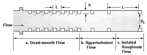
The following figure shows the flow regimes and variables for an increased resistance energy dissipator implemented in a circular culvert.
Variables from the figure
- L -- Length from beginning of one roughness element to the beginning of the next roughness element.
- h -- height of roughness element
- Di -- diameter of roughened section (opening)
