HY8:Box Inlet Drop Structure
From XMS Wiki
Jump to navigationJump to search
The input variables required for this calculation is the following:
- HD -- Desired drop height. Must be between 2 and 12 ft or between 0.6 and 3.7 m.
- New Slope -- The slope that will exist on the channel once the drop structures are in place (The new slope must be subcritical).
- Box Length -- Length of box inlet. (USER'S CHOICE)
- W2 -- Width of box inlet. Must fit criteria (.25 < HD/W2 < 1)
- W3 -- Width of the Downstream End of Stilling Basin. This must be equal to or larger than the culvert width.
Flare of Stilling Basin (1 Lateral: Z long) -- This value must be greater than or equal to 2, which is to say 1 lateral: 2 Long)
Length from Toe of Dike to Box Inlet -- If a dike is used, the distance from the toe of the dike to the box inlet must be entered. If no dike is used, enter a value of 100 ft or 30.48 m for this distance.
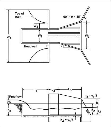
The following figure shows a plan and side view of a box inlet drop structure.
Variables from the figure
- W1 -- Width of the upstream end of the basin
- W2 -- Width of box inlet crest
- W3 -- Width of the downstream end of the basin
- W4 -- Distance from the toe of dike to the box inlet
- L1 -- Length of box inlet
- L2 -- Minimum length for the straight section
- L3 -- Minimum length for final section (potentially flared)
- H0 -- Drop from crest to stilling basin floor
- h2 -- Vertical distance of the tailwater below the crest
- h3 -- Height of the end sill
- y0 -- Required head on the weir crest to pass the design flow
- y3 -- Tailwater depth above the floor of the stilling basin
- h4 -- Sill height
