SMS:EFDC Coverage
| This article is for a model that is under development by Aquaveo and its partners. The model is not available to the public at this time. It is not known when or if the model will be released. The content may not apply to current or older versions. |
The EFDC coverage is used to create curvilinear grids for use with the EFDC model (EFDC grid format). A curvilinear grid has I and J coordinates but the cells do not have to follow straight lines like rectilinear grids see Curvilinear Grid Module.
The coverage doesn't contain any point or arc attributes.
The EFDC coverages uses the same meshing tools as other SMS coverages but with limited options. The only supported meshing option is rectangular patches. Patches cannot have transitions (all opposing sides must have the same number of vertices). See Mesh Generation for more information about the meshing options available in SMS.
EFDC Model Control
The EFDC Model Control dialog is accessed using the EFDC | Model Control... menu item or by right-clicking on the EFDC simulation and selecting the Model Control command.
Dialog Description
The EFDC Model Control contains the following pages:
General
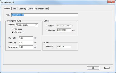
The General tab of the EFDC Model Control is used to specify general simulation parameters. It contains the following controls:
Title
Text description up to 80 characters in length for the run. EFDC.inp card 1.1
Wetting and drying
- Method – Wetting and drying method. EFDC.inp card 5.5
- None
- Constant Depth
- Nonlinear iteration
- Cell masking
- Variable Depth
- Cell masking
- Cell faces
- Dry depth – Depth at which cell or flow face becomes dry. EFDC.inp card 11.10
- Depth adj – Adjustment to bottom bed elevation field in meters. EFDC.inp card 11.12
- Layer const – Log bdry layer const or variable rough height adj in meters. EFDC.inp card 11.5
Coriolis
- Latitude – The coriolis parameter will be calculated by SMS from the specified latitude value. EFDC.inp card 8.4
- Constant – Constant coriolis parameter in 1/sec. EFDC.inp card 8.4
Solver
- Residual – Target square residual of iterative solution scheme. EFDC.inp card 3.2
Time
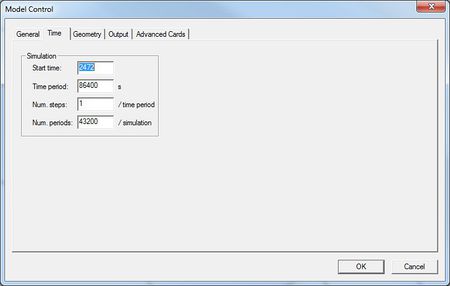
The Time tab of the EFDC Model Control is used to specify simulation time parameters. It contains the following controls:
Simulation
- Start time – Time origin of the run. EFDC.inp card 8.2
- Time period – Reference time period in seconds. EFDC.inp card 8.3
- Num. steps – Number of time steps per reference time period. EFDC.inp card 7.2
- Num. periods – Number of reference time periods in run. EFDC.inp card 7.1
Geometry
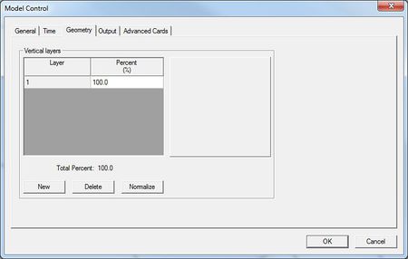
The Geometry tab of the EFDC mMdel Control is used to specify geometry related parameters for the simulation. It contains the following controls:
Vertical Layers
The number of layers specified in the vertical layers spreadsheet is used for the value of EFDC.inp card 9.1.
- Layer – Layer number. Use the New and Delete buttons to create / remove layers. EFDC.inp card 10.1
- Percent – Dimensionless layer thickness. Must sum to 100%. EFDC.inp card 10.2
Output
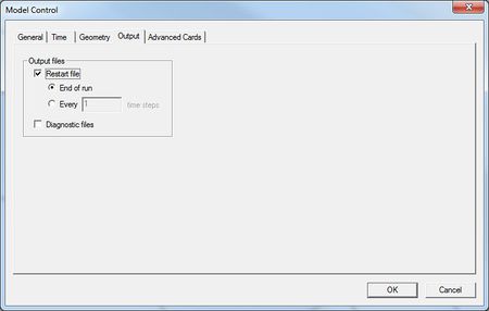
The Output tab of the EFDC Model Control is used to specify the output the model will create. It contains the following controls:
Output Files
- Restart file
- End of run – Restart file written at the end of the run. EFDC.inp card 2.2
- Every <> time steps – Restart file written every <> time periods. EFDC.inp card 2.2
Advanced Cards
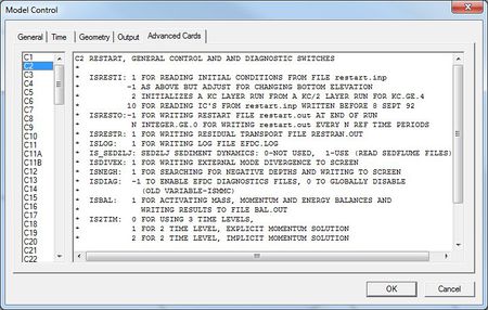
The Advanced Cards tab of the EFDC Model Control is used to modify advanced simulation parameters not supported directly in the Model Control.
Dialog Description
The text blocks associated with a given card can be edited directly in the dialog. A list of the cards available to edit is shown on the left of the dialog. The fields corresponding to the card parameters directly supported by SMS will be overwritten when the dialog is exited.
SMS – Surface-water Modeling System | ||
|---|---|---|
| Modules: | 1D Grid • Cartesian Grid • Curvilinear Grid • GIS • Map • Mesh • Particle • Quadtree • Raster • Scatter • UGrid |  |
| General Models: | 3D Structure • FVCOM • Generic • PTM | |
| Coastal Models: | ADCIRC • BOUSS-2D • CGWAVE • CMS-Flow • CMS-Wave • GenCade • STWAVE • WAM | |
| Riverine/Estuarine Models: | AdH • HEC-RAS • HYDRO AS-2D • RMA2 • RMA4 • SRH-2D • TUFLOW • TUFLOW FV | |
| Aquaveo • SMS Tutorials • SMS Workflows | ||
