HY8:Increased Resistance in Culverts
From XMS Wiki
Jump to navigationJump to search
The increased resistance dissipator type can be used for either box culverts or circular culverts. Variables for these energy dissipators are described below.
Increased Resistance in Box Culverts
The input variables required for this calculation are the following:
- h/ri—Ratio of roughness element height divided by hydraulic radius taken about the top of the roughness element.
- Height of the roughened section (h)
Increased Resistance in Circular Culverts
The input variables required for this calculation is the following:
- L/Di — Ratio of roughness element spacing divided by the diameter of the culvert opening at the roughness element. (Range = .05 to 1.5)
- h/Di — Ratio of roughness element height divided by the diameter of the culvert opening at the roughness element. (Range = .005 to .1).
- Lr/Pi — Ratio of the roughness length to inside perimeter (Range = 0.0 to 1.0)
- Diameter of roughened section (Opening, Di)
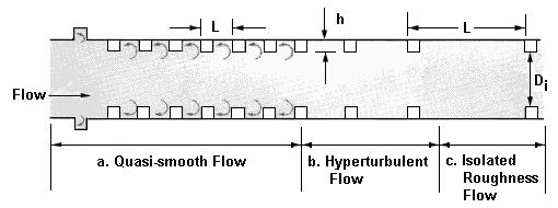
The following figure shows the flow regimes and variables for an increased resistance energy dissipator implemented in a circular culvert.
Variables from the figure
- L — Length from beginning of one roughness element to the beginning of the next roughness element.
- h — height of roughness element
- Di — diameter of roughened section (opening)
