HY8:Polynomial Coefficients
For circular, box, elliptical, pipe arch, and concrete open-bottom arch (commonly called CON/SPAN) culverts, polynomial coefficients, found in Tables 1-5, are utilized in the inlet control headwater computations. Tables 6-10 show the HW/D points A(1) through A(10) for interpolation. Each row of coefficients represents different entrance conditions for different culvert shapes.
Table 1. Polynomial Coefficients - Circular
| HY-8 Equation | Edge Condition | KE | SR | A | BS | C | DIP | EE | F |
|---|---|---|---|---|---|---|---|---|---|
|
1 |
Thin Edge Projecting |
0.9 |
0.5 |
0.187321 |
0.56771 |
-0.156544 |
0.0447052 |
-0.00343602 |
8.96610E-05 |
|
2 |
Mitered to Conform to Slope |
0.7 |
-0.7 |
0.107137 |
0.757789 |
-0.361462 |
0.1233932 |
-0.01606422 |
0.00076739 |
|
3 |
Square Edge with Headwall (Steel/Aluminum/Corrugated PE) |
0.5 |
0.5 |
0.167433 |
0.538595 |
-0.149374 |
0.0391543 |
-0.00343974 |
0.000115882 |
|
4 |
Grooved End Projecting |
0.2 |
0.5 |
0.108786 |
0.662381 |
-0.233801 |
0.0579585 |
-0.0055789 |
0.000205052 |
|
5 |
Grooved End in Headwall |
0.2 |
0.5 |
0.114099 |
0.653562 |
-0.233615 |
0.0597723 |
-0.00616338 |
0.000242832 |
|
6 |
Beveled Edge (1:1) |
0.2 |
0.5 |
0.063343 |
0.766512 |
-0.316097 |
0.0876701 |
-0.009836951 |
0.00041676 |
|
7 |
Beveled Edge (1.5:1) |
0.2 |
0.5 |
0.08173 |
0.698353 |
-0.253683 |
0.065125 |
-0.0071975 |
0.000312451 |
|
8 |
sq. proj. |
0.2 |
0.5 |
0.167287 |
0.558766 |
-0.159813 |
0.0420069 |
-0.00369252 |
0.000125169 |
|
9 |
Square Edge with Headwall (Concrete/PVC/HDPE) |
0.5 |
0.5 |
0.087483 |
0.706578 |
-0.253295 |
0.0667001 |
-0.00661651 |
0.000250619 |
|
10 |
end sect. |
0.4 |
0.5 |
0.120659 |
0.630768 |
-0.218423 |
0.0591815 |
-0.00599169 |
0.000229287 |
EQ #'s: REFERENCE
1-9 : Calculator Design Series (CDS) 3 for TI-59, FHWA, 198O, page 60
1-10: Hydraulic Computer Program (HY) 1, FHWA, 1969, page 18
Table 2. Polynomial Coefficients - Box
| HY-8 Equation | Edge Condition | KE | SR | A | BS | C | DIP | EE | F |
|---|---|---|---|---|---|---|---|---|---|
|
1 |
Square Edge (90 degree) Headwall Square Edge (90 & 15 degree flare) Wingwall |
0.5 |
0.5 |
0.122117 |
0.505435 |
-0.10856 |
0.0207809 |
-0.00136757 |
0.00003456 |
|
2 |
1.5:1 Bevel (90 degree) Headwall |
0.2 |
0.5 |
0.0967588 |
0.4551575 |
-0.08128951 |
0.01215577 |
-0.00067794 |
0.0000148 |
|
3 |
1:1 Bevel Headwall |
0.2 |
0.5 |
0.1566086 |
0.3989353 |
-0.06403921 |
0.01120135 |
-0.0006449 |
0.000014566 |
|
4 |
Square Edge (30-75 degree flare) Wingwall |
0.4 |
0.5 |
0.0724927 |
0.507087 |
-0.117474 |
0.0221702 |
-0.00148958 |
0.000038 |
|
5 |
Square Edge (0 degree flare) Wingwall |
0.7 |
0.5 |
0.144133 |
0.461363 |
-0.0921507 |
0.0200028 |
-0.00136449 |
0.0000358 |
|
6 |
1:1 Bevel (45 degree flare) Wingwall 1.5:1 Bevel (19-34 degree flare) Wingwall |
0.2 |
0.5 |
0.0895633 |
0.4412465 |
-0.07434981 |
0.01273183 |
-0.0007588 |
0.00001774 |
EQ #'s: REFERENCE
1-6: Hydraulic Computer Program (HY) 6, FHWA, 1969, subroutine BEQUA
1,4,5: Hydraulic Computer Program (HY) 3, FHWA, 1969, page 16
1,3,4,6: Calculator Design Series (CDS) 3 for TI-59, FHWA, 1980, page 16
Table 3. Polynomial Coefficients - Ellipse
EQ #'s: REFERENCE
27-30: Calculator Design Series (CDS) 4 for TI-59, FHWA, 1982, page 20
31-33: Calculator Design Series (CDS) 4 for TI-59, FHWA, 1982, page 22
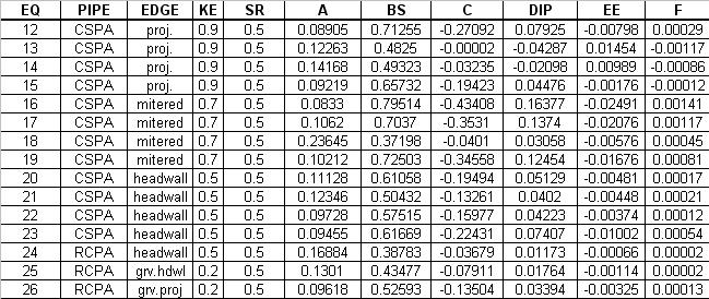
Table 4. Polynomial Coefficients - Pipe Arch
EQ #'s: REFERENCE
12-23: Calculator Design Series (CDS) 4 for TI-59, FHWA, 1982, page 17
24-26: Calculator Design Series (CDS) 4 for TI-59, FHWA, 1982, page 24
12,16,20: Hydraulic Computer Program (HY) 2, FHWA, 1969, page 17
Table 5. Polynomial Coefficients - Concrete Open-Bottom Arch
| Span:Rise Ratio | Wingwall Angle (Inlet Edge Condition) | KE | SR | A | BS | C | DIP | EE | F | Diagram/Notes |
|---|---|---|---|---|---|---|---|---|---|---|
| 2:1 |
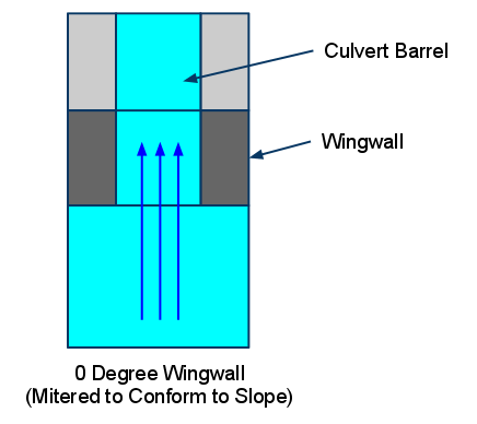
0 Degrees (Mitered to Conform to Slope) |
0.7 |
0.0 |
0.0356 |
0.5701 |
-0.162 |
0.0322 |
-0.0023 |
0.00006 |
2:1 Coefficients are used if the span:rise ratio is less than or equal to 3:1. |
| 2:1 |
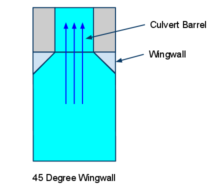
45 Degrees (45-degree Wingwall) |
0.5 |
0.0 |
0.0393 |
0.5828 |
-0.1518 |
0.0284 |
-0.002 |
0.00005 |
2:1 Coefficients are used if the span:rise ratio is less than or equal to 3:1. |
| 2:1 |
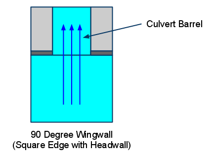
90 Degrees (Square Edge with Headwall) |
0.5 |
0.0 |
0.0459 |
0.5762 |
-0.1436 |
0.0269 |
-0.0019 |
0.00005 |
2:1 Coefficients are used if the span:rise ratio is less than or equal to 3:1. |
| 4:1 |
0 Degrees (Mitered to Conform to Slope) |
0.7 |
0.0 |
0.0309 |
0.5211 |
-0.1258 |
0.0207 |
-0.0013 |
0.00003 |
4:1 coefficients are used if the span:rise ratio is greater than 3:1 |
| 4:1 |
45 Degrees (45-degree Wingwall) |
0.5 |
0.0 |
0.0318 |
0.5446 |
-0.1467 |
0.0273 |
-0.0019 |
0.00005 |
4:1 coefficients are used if the span:rise ratio is greater than 3:1 |
| 4:1 |
90 Degrees (Square Edge with Headwall) |
0.5 |
0.0 |
0.0283 |
0.5739 |
-0.1584 |
0.0292 |
-0.002 |
0.00005 |
4:1 coefficients are used if the span:rise ratio is greater than 3:1 |
References for Concrete Open-bottom Arch polynomial coefficients:
- Thiele, Elizabeth A. Culvert Hydraulics: Comparison of Current Computer Models. (pp. 121-126), Brigham Young University Master's Thesis (2007).
- Chase, Don. Hydraulic Characteristics of CON/SPAN Bridge Systems. Submitted Study and Report (1999)
Table 6. Polynomial Coefficients - South Dakota Concrete Box
| Description | KE | SR | A | BS | C | DIP | EE | F | Diagram/Notes |
|---|---|---|---|---|---|---|---|---|---|
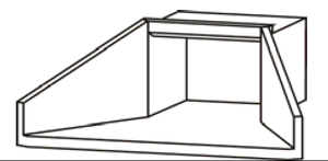
| Sketch 1: 30 degree-flared wingwalls; top edge beveled at 45 degrees |
0.5 |
0.5 |
0.0176998563 |
0.5354484847 |
-0.1197176702 |
0.0175902318 |
-0.0005722076 |
-0.0000080574 |
|
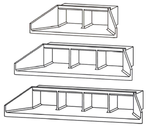
| Sketch 2: 30 degree-flared wingwalls; top edge beveled at 45 degrees; 2, 3, and 4 multiple barrels |
0.5 |
0.5 |
0.0506647261 |
0.5535393634 |
-0.1599374238 |
0.0339859269 |
-0.0027470036 |
0.0000851484 |
|
| Sketch 3: 30 degree-flared wingwalls; top edge beveled at 45 degrees; 2:1 to 4:1 span-to-rise ratio |
0.5 |
0.5 |
0.0518005829 |
0.5892384653 |
-0.1901266252 |
0.0412149379 |
-0.0034312198 |
0.0001083949 |
|
| Sketch 4: 30 degree-flared wingwalls; top edge beveled at 45 degrees; 15 degrees skewed headwall with multiple barrels |
0.5 |
0.5 |
0.2212801152 |
0.6022032341 |
-0.1672369732 |
0.0313391792 |
-0.0024440549 |
0.0000743575 |
|
| Sketch 5: 30 degree-flared wingwalls; top edge beveled at 45 degrees; 30 degrees to 45 degrees skewed headwall with multiple barrels |
0.5 |
0.5 |
0.2431604850 |
0.5407556631 |
-0.1267568901 |
0.0223638322 |
-0.0016523399 |
0.0000490932 |
|
| Sketches 6 & 7: 0 degree-flared wingwalls (extended sides); square-edged at crown and 0 degree-flared wingwalls (extended sides); top edge beveled at 45 degrees; 0- and 6-inch corner fillets |
0.5 |
0.5 |
0.0493946080 |
0.7138391179 |
-0.2354755894 |
0.0473247331 |
-0.0036154348 |
0.0001033337 |
|
| Sketches 8 & 9: 0 degree-flared wingwalls (extended sides); top edge beveled at 45 degrees; 2, 3, and 4 multiple barrels and 0 degree-flared wingwalls (extended sides); top edge beveled at 45 degrees; 2:1 to 4:1 span-to-rise ratio |
0.5 |
0.5 |
0.1013668008 |
0.6600937637 |
-0.2133066786 |
0.0437022641 |
-0.0035224589 |
0.0001078198 |
|
| Sketches 10 & 11: 0 degree-flared wingwalls (extended sides); crown rounded at 8-inch radius; 0- and 6-inch corner fillets and 0 degree-flared wingwalls (extended sides); crown rounded at 8-inch radius; 12-inch corner fillets |
0.5 |
0.5 |
0.0745605288 |
0.6533033536 |
-0.1899798824 |
0.0350021004 |
-0.0024571627 |
0.0000642284 |
|
| Sketch 12: 0 degree-flared wingwalls (extended sides); crown rounded at 8-inch radius; 12-inch corner fillets; 2, 3, and 4 multiple barrels |
0.5 |
0.5 |
0.1321993533 |
0.5024365440 |
-0.1073286526 |
0.0183092064 |
-0.0013702887 |
0.0000423592 |
|
| Sketch 13: 0 degree-flared wingwalls (extended sides); crown rounded at 8-inch radius; 12-inch corner fillets; 2:1 to 4:1 span-to-rise ratio. |
0.5 |
0.5 |
0.1212726739 |
0.6497418331 |
-0.1859782730 |
0.0336300433 |
-0.0024121680 |
0.0000655665 |
References for South Dakota Concrete Box polynomial coefficients:
- Thiele, Elizabeth A. Culvert Hydraulics: Comparison of Current Computer Models. (pp. 121-126), Brigham Young University Master's Thesis (2007).
- Effects of Inlet Geometry on Hydraulic Performance of Box Culverts (FHWA Publication No. FHWA-HRT-06-138, October 2006)
Table 6. Arch HW/D Values.
Table 7. High Profile Arch HW/D Values.
Table 8. Low Profile Arch HW/D Values.
Table 9. Metal Box HW/D Values.
Table 10. User Defined HW/D Values.

