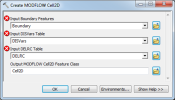
AHGW:Create MODFLOW Cell2D
From XMS Wiki
Jump to navigationJump to search
The Create MODFLOW Cell2D tool is accessed by double-clicking on "![]() Create MODFLOW Cell2D" under the "
Create MODFLOW Cell2D" under the "![]() Features" toolset under the "
Features" toolset under the "![]() MODFLOW Analyst" toolset under the "
MODFLOW Analyst" toolset under the "![]() Arc Hydro Groundwater Tools" toolbox.
Arc Hydro Groundwater Tools" toolbox.
The following fields are available. Fields marked with a ![]() icon may either not be supported or the table doesn't exist.
icon may either not be supported or the table doesn't exist.
- Input Boundary Features – Click the
 button to bring up the Input Boundary Features dialog in order to specify the layer in which to build the boundary rectangle polygon.
 - Input DISVars Table – Click the
 button to bring up the Input DISVars Table dialog in order to specify the DISVars table contains variables associated with the DIS file. It must contain NLAY, NROW, and NCOL fields which define the number of layers, rows, and columns in the grid associated with the MODFLOW Data Model.
 - Input DELRC Table – Click the
 button to bring up the Input DELRC Table dialog in order to specify the DELRC table is used to store the widths (discretization) of the rows and columns associated with the MODFLOW model. It must contain Direction, Num, and Width fields.
 - Output MODFLOW Cell2D Feature Class – Click the
 button to bring up the Input Boundary Features dialog in order to specify the Cell2D feature polygons to be created.

