GMS:Horizons Wizard: Difference between revisions

From XMS Wiki
Jump to navigationJump to search
Line 8: Line 8:


[[File:HorizonsWizard1.png|thumb|none|500 px|The ''Horizon Elevation'' step of the ''Horizons'' wizard]]
[[File:HorizonsWizard1.png|thumb|none|500 px|The ''Horizon Elevation'' step of the ''Horizons'' wizard]]
===Including Borehole Cross Sections===
If the Horizon process using horizons on borehole contacts does not produce the desired results, the borehole data can be supplemented with [[GMS:Borehole Cross Sections|user-defined cross sections]] using the [[GMS:Borehole Cross Sections|''Cross Section Editor'']].
For example, when the '''Horizons → Solids''' command is executed, the user can choose to include cross section data.  If this option is selected, the material boundaries (arcs) on the cross sections inherit the horizon ID assigned to the adjacent borehole contact and the points along the material boundary are added to the contacts when interpolating the horizon surfaces.  The resulting solids match the user-defined cross sections as closely as possible.  In other words, by creating a few simple cross section, the user has complete control over the shape of the solids created by the horizons technique.
The match between the resulting solid and the user defined cross section is a function of two things: first, the density of the points on the user defined cross section, and second the triangle density of the primary TIN.  As mentioned, the arcs on the cross sections inherit the horizon ID from the borehole contact as shown below.
[[Image:xsect_hor.jpg|none|frame|Example of how cross section data inherits horizon id from boreholes]]
In this case the marked points on the cross section inherit horizon ID 3.  If wanting more control over the interpolation of horizon 3, then add more points to the arc. This can be done by selecting the '''Select Arc''' tool's right-click '''Redistribute Virtices''' command in the ''Cross Section Editor''.  The triangle density of the primary TIN also controls how well the resulting solid matches the user-defined cross section.  Since the points on the cross section are interpolated to the primary TIN, if the TIN does not have a significant number of triangles in the vicinity of the cross section then there is no way the TIN surface can match the cross section.


==Step 2==
==Step 2==

Revision as of 21:14, 27 September 2017

Horizons
HorCoverage.png
Links
Horizons
Horizons to Solids
Horizons to 3D Mesh
Horizons to UGrid
Horizons to HUF
Horizons Wizard
Including Borehole Cross Sections
Raster Catalog
Horizons Conceptual Model
Horizons Applications

The Horizons Wizard is used to create solids, a 3D mesh, or HUF layers from horizon data. The wizard is started via the Horizons → Solids, Horizons → 3D Mesh, Horizons → UGrid, and Horizons → HUF commands. These commands are in the TIN and Boreholes menus.

Step 1

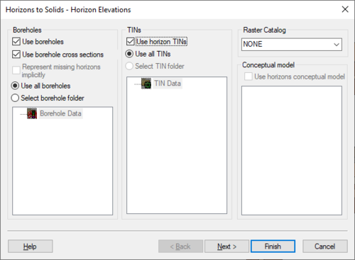
The first step is to define the inputs to be used, which can include boreholes, TINs, and a Horizon Conceptual model.

Beginning with GMS 9.0, a raster catalog can be included as input.

The Horizon Elevation step of the Horizons wizard

Including Borehole Cross Sections

If the Horizon process using horizons on borehole contacts does not produce the desired results, the borehole data can be supplemented with user-defined cross sections using the Cross Section Editor.

For example, when the Horizons → Solids command is executed, the user can choose to include cross section data. If this option is selected, the material boundaries (arcs) on the cross sections inherit the horizon ID assigned to the adjacent borehole contact and the points along the material boundary are added to the contacts when interpolating the horizon surfaces. The resulting solids match the user-defined cross sections as closely as possible. In other words, by creating a few simple cross section, the user has complete control over the shape of the solids created by the horizons technique.

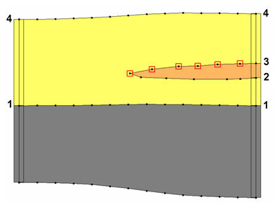
The match between the resulting solid and the user defined cross section is a function of two things: first, the density of the points on the user defined cross section, and second the triangle density of the primary TIN. As mentioned, the arcs on the cross sections inherit the horizon ID from the borehole contact as shown below.

Example of how cross section data inherits horizon id from boreholes

In this case the marked points on the cross section inherit horizon ID 3. If wanting more control over the interpolation of horizon 3, then add more points to the arc. This can be done by selecting the Select Arc tool's right-click Redistribute Virtices command in the Cross Section Editor. The triangle density of the primary TIN also controls how well the resulting solid matches the user-defined cross section. Since the points on the cross section are interpolated to the primary TIN, if the TIN does not have a significant number of triangles in the vicinity of the cross section then there is no way the TIN surface can match the cross section.

Step 2

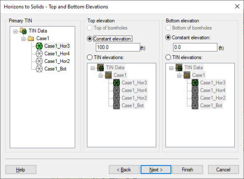
The second step is to define the top and bottom of the solid, mesh, or HUF layers. When creating HUF data, the grid elevations can be edited.

The Top and Bottom Elevations step of the Horizons wizard

Step 3

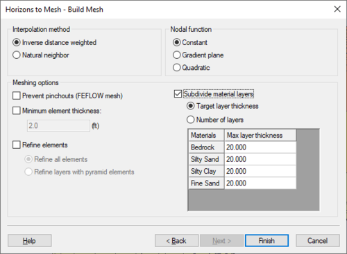
The Build Mesh step of the Horizons wizard

The third step is to define the interpolation method to be used, as well as options specific to creating solids, a mesh, or HUF package.

Beginning with GMS 7.0, when creating solids, the user can choose the option Preserve projection TIN datasets. This option will create a new TIN that will have a dataset for each horizon. This is often useful so that the user can see the result of the interpolation process for each Horizon. The user can then edit the TIN by hand and include the TIN when executing the Horizons→Solids command.

When creating a 3D mesh for a FEFLOW simulation, make sure to turn on the Prevent pinchouts (FEFLOW mesh) option. This will ensure that the mesh will contain all prism elements and that every mesh layer is continuous throughout the mesh.