HY8:AOP SS Align and Size Culvert
AOP Stream Simulation, Align and Size Culvert
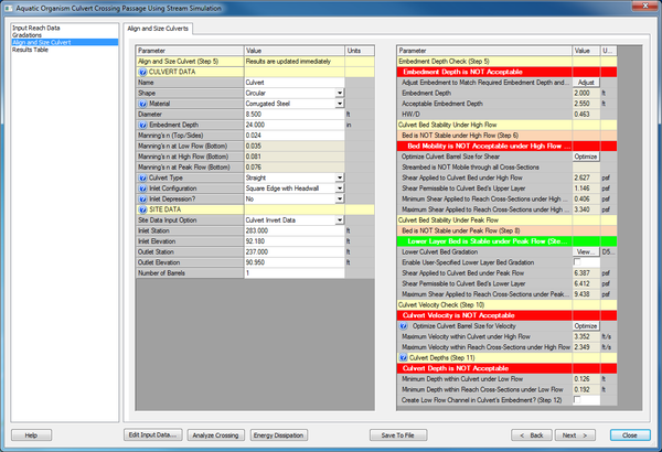
This dialog will allow you to make changes to the layout and size of your culvert and immediately see the results in the Aquatic Organism Passage. It will also allow you to hit a button, and have HY-8 change the size of the culvert until it is the smallest culvert barrel size that still allows passage for shear, and then for shear and velocity. Before you optimize the culvert, you need to verify that the site data of the culvert is correct. Also recognize that there is no undo or cancel on optimize or any changes made to the culvert alignment and size.
Align and Size Culverts
The left side of the dialog contains the same spreadsheet that is available on the right side of the Crossing Input Data dialog. Any changes made on this page, will change the data that is shown in that dialog. There is no undo or cancel on this page. More information is available at Culvert Data
Aquatic Organism Passage Results
Embedment Depth Check
The Right side of the dialog reports the Aquatic Organism Passage results. It starts with the embedment level. The level of embedment depends on the layers that are required, the gradations of those layers, and the shape of the culvert. There is a button that will adjust the embedment to match the required amount of embedment. This may change the invert elevations of your culvert as well as the embedment depth. The headwater depth over culvert rise, HW/D, is also reported in this section so the user can verify that the culvert still meets hydraulic design criteria. This calculation does not include the section of culvert that is embedded when calculating the rise and the headwater depth.
Culvert Bed Stability Under High Flows
Next is the stability of the culvert bed under High Flow. First, it checks if the culvert bed's upper layer is stable under high flow. It does this by comparing the shear applied to the shear permissible to the culvert bed's upper layer. If the permissible shear is greater, then it is stable. If that fails, the bed mobility may still be acceptable. First HY-8 determines if the streambed is mobile. If the applied shear on all cross-section are above the permissible shear, then all cross-section will be eroding and the streambed will be mobile. If the bed is mobile and as long as the shear applied to the culvert bed, is less than the maximum shear applied to the cross-sections immediately upstream or downstream of the culvert crossing, then the mobility is acceptable. If the bed is NOT mobile or if the culvert's shear is higher than the maximum shear in the cross sections, it is not acceptable.
For more information on the optimize button, see below.
Culvert Bed Stability Under Peak Flows
The next section is where HY-8 checks the stability of the culvert bed under Peak flow. First it checks if the culvert bed's upper layer is stable under peak flow. It does this by comparing the shear applied to the shear permissible to the culvert bed's upper layer. If the permissible shear is greater, then it is stable. If it is unstable, HY-8 will determine the gradation that will be stable. The user can then specify their own gradation to be used in the calculations. For the user's ability to compare, the maximum shear applied to the reach cross-section under peak flow is reported, although it is not used in these calculations.
Culvert Velocity Check
The third check is the velocity under high flow. HY-8 determines the maximum average velocity within the barrel when it determines the water surface elevations through direct step. It then compares this velocity with the maximum average velocity computed using the Manning's Equation at the cross-sections. As long as the culvert's velocity is less than the velocity in the cross-sections, the velocity is acceptable.
The optimize routine increases the barrel size to decrease the culvert barrel velocity. As this is not the most effective way of decreasing the velocity, this routine is often unstable. Each time you click the optimization routine, it will not increase the barrel size more than 2'. The designer should keep in mind the allowable tolerances of the velocities and whether a velocity that is still higher than the maximum cross-section channel velocity, may still be acceptable. For example, a velocity slightly higher than those in the natural channel, but over a much shorter flow length within the culvert, compared to the flow lengths in the natural channel. Also, the velocities are determined through different methods: the culvert velocity is computed through the direct step method while the reach cross-sections are determined through normal depth. Finally, if the velocity is significantly higher than the reach cross-sections, the engineer should consider a change in the slope of the culvert.
For more information on the optimize button, see below.
Culvert Depths
The final check is the depth in the culvert under low flow. HY-8 determines the minimum depth within the barrel when it determines the water surface elevations through direct step. It then compares the minimum depth in the culvert, with the minimum depth in the cross section that is computed by the Manning's Equation.
If the depth is too shallow, the user can create a low flow channel in the embedment. The side slope of the low flow channel is 1:8 (V:H), but the depth can be adjusted by the user. The shape of the embedded culvert will be modified in the computations and in the front view of the culvert. This change will affect the computations in the Culvert Crossing Output Dialog as well.
It is difficult to meet the minimum depth requirements, even with a well-designed culvert crossing. The user should remember that the two depths are computed differently: the minimum depth in the culvert is determined through the direct step method while the minimum depth in the reach cross-sections are determined by normal depth. The user should make their best effort to maintain the minimum depth, including specifying a low flow channel, but once these options have been exhausted, there is little more that can be done to improve the design and aquatic organism passage. The best possible design should be accepted at that point.
Optimize Culvert Barrel Size
Near the bottom of this dialog is the 'Optimize Culvert Barrel Size'. This will change the size of the culvert barrel to 4' and turn off the low flow channel. HY-8 will then increase the barrel size until the culvert bed is stable (or acceptable). If the optimize button in the velocities section is clicked, then HY-8 will continue to increase the size of barrel until the velocity is acceptable.
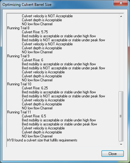
HY-8 will launch the Optimize dialog that will show each calculation being performed and the result of that run. It will also allow you to cancel if HY-8 is taking too long to optimize. Eventually, HY-8 will give up on finding an optimized culvert.
The Optimization routine will modify the values of the culvert barrel size that will change the results in the AOP dialog and the Culvert Crossing Input Data and the View Culvert Crossing Results Dialog. There is no undo or cancel on this option. It is recommended that if you wish to be able to return to the state before optimizing the culvert size, that you save the crossing to a file.

