HY8:Colorado State University (CSU) Rigid Boundary Basin: Difference between revisions
From XMS Wiki
Jump to navigationJump to search
No edit summary |
No edit summary |
||
| Line 2: | Line 2: | ||
No input variables are required for this calculation; however, one design is selected by the user. | No input variables are required for this calculation; however, one design is selected by the user. | ||
All possible designs for CSU Rigid Boundary Basins are calculated for the given culvert and flow. Designs which do not dissipate sufficient energy are discarded. The criteria of the remaining designs are numbered and displayed one at a time. | All possible designs for CSU Rigid Boundary Basins are calculated for the given culvert and flow. Designs which do not dissipate sufficient energy are discarded. The criteria of the remaining designs are numbered and displayed one at a time. | ||
| Line 8: | Line 7: | ||
Designs are calculated and displayed in order of increasing width, increasing number of element rows, and increasing element height. As a result, smaller, less expensive designs are presented first. | Designs are calculated and displayed in order of increasing width, increasing number of element rows, and increasing element height. As a result, smaller, less expensive designs are presented first. | ||
The following figures show a Colorado State University (CSU) Rigid Boundary Basin | The following figures show a Colorado State University (CSU) Rigid Boundary Basin | ||
| Line 16: | Line 14: | ||
Variables from the figure | Variables from the figure | ||
* | * W<sub>0</sub> -- Culvert width at culvert outlet | ||
* | * W<sub>1</sub> -- Element width which is equal to element spacing | ||
* h -- Roughness element height | * h -- Roughness element height | ||
| Line 24: | Line 22: | ||
Variables from the figure | Variables from the figure | ||
* | * V<sub>0</sub> -- Velocity at the culvert outlet | ||
* | * V<sub>A</sub> -- Approach velocity at two culvert widths downstream of the culvert outlet | ||
* | * V<sub>B</sub> -- Exit velocity, just downstream of the last row of roughness elements | ||
* | * y<sub>0</sub> -- Depth at the culvert outlet | ||
* | * y<sub>A</sub> -- Approach depth at two culvert widths downstream of the culvert outlet | ||
* | * y<sub>B</sub> -- Depth at exit | ||
* | * W<sub>0</sub> -- Culvert width at the culvert outlet | ||
* | * L<sub>B</sub> -- Total basin length | ||
* L -- Longitudinal spacing between rows of elements | * L -- Longitudinal spacing between rows of elements | ||
| Line 38: | Line 36: | ||
Variables from the figure | Variables from the figure | ||
* | * W<sub>B</sub> -- Width of basin | ||
* | * W<sub>0</sub> -- Culvert width at the culvert outlet | ||
* L -- Longitudinal spacing between rows of elements | * L -- Longitudinal spacing between rows of elements | ||
* | * N<sub>r</sub> -- Row number | ||
{| Border=5 CellPadding=3 CellSpacing=0 | {| Border=5 CellPadding=3 CellSpacing=0 | ||
Revision as of 21:29, 16 December 2011
Colorado State University (CSU) Rigid Boundary Basin
No input variables are required for this calculation; however, one design is selected by the user.
All possible designs for CSU Rigid Boundary Basins are calculated for the given culvert and flow. Designs which do not dissipate sufficient energy are discarded. The criteria of the remaining designs are numbered and displayed one at a time.
Designs are calculated and displayed in order of increasing width, increasing number of element rows, and increasing element height. As a result, smaller, less expensive designs are presented first.
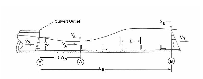
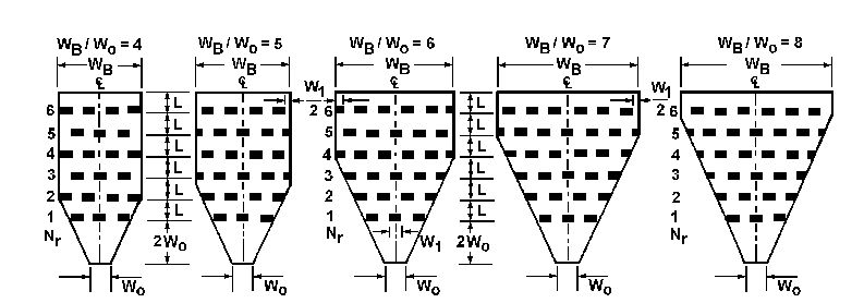
The following figures show a Colorado State University (CSU) Rigid Boundary Basin
Variables from the figure
- W0 -- Culvert width at culvert outlet
- W1 -- Element width which is equal to element spacing
- h -- Roughness element height
Variables from the figure
- V0 -- Velocity at the culvert outlet
- VA -- Approach velocity at two culvert widths downstream of the culvert outlet
- VB -- Exit velocity, just downstream of the last row of roughness elements
- y0 -- Depth at the culvert outlet
- yA -- Approach depth at two culvert widths downstream of the culvert outlet
- yB -- Depth at exit
- W0 -- Culvert width at the culvert outlet
- LB -- Total basin length
- L -- Longitudinal spacing between rows of elements
Variables from the figure
- WB -- Width of basin
- W0 -- Culvert width at the culvert outlet
- L -- Longitudinal spacing between rows of elements
- Nr -- Row number
| WB/W0 | 2 to 4 | 5 | 6 | 7 | 8 | |||||||||
|---|---|---|---|---|---|---|---|---|---|---|---|---|---|---|
| W1/W0 | 0.57 | 0.63 | 0.6 | 0.58 | .62 | |||||||||
| Rows (Nr) | 4 | 5 | 6 | 4 | 5 | 6 | 4 | 5 | 6 | 5 | 6 | 6 | ||
| Elements (N) | 14 | 17 | 21 | 15 | 19 | 23 | 17 | 22 | 27 | 24 | 30 | 30 | ||
| Rectangular | h/ya | L/h | Basin Drag Coefficient, CB | |||||||||||
| .91 | 6 | 0.32 | 0.28 | 0.24 | 0.32 | 0.28 | 0.24 | 0.31 | 0.27 | 0.23 | 0.26 | 0.22 | 0.22 | |
| .71 | 6 | 0.44 | 0.40 | 0.37 | 0.42 | 0.38 | 0.35 | 0.40 | 0.36 | 0.33 | 0.34 | 0.31 | 0.29 | |
| 0.48 | 12 | 0.60 | 0.55 | 0.51 | 0.56 | 0.51 | 0.47 | 0.53 | 0.48 | 0.43 | 0.46 | 0.39 | 0.35 | |
| 0.37 | 12 | 0.68 | 0.66 | 0.65 | 0.65 | 0.62 | 0.60 | 0.62 | 0.58 | 0.55 | 0.54 | 0.50 | 0.45 | |
| Circular | 0.91 | 6 | 0.21 | 0.20 | 0.48 | 0.21 | 0.19 | 0.17 | 0.21 | 0.19 | 0.17 | 0.18 | 0.16 |  # |
| 0.71 | 6 | 0.29 | 0.27 | 0.40 | 0.27 | 0.25 | 0.23 | 0.25 | 0.23 | 0.22 | 0.22 | 0.20 |  # | |
| 0.31 | 6 | 0.38 | 0.36 | 0.34 | 0.36 | 0.34 | 0.32 | 0.34 | 0.32 | 0.30 | 0.30 | 0.28 |  # | |
| 0.48 | 12 | 0.45 | 0.42 | 0.25 | 0.40 | 0.38 | 0.36 | 0.36 | 0.34 | 0.32 | 0.30 | 0.28 |  # | |
| 0.37 | 12 | 0.52 | 0.50 | 0.18 | 0.48 | 0.46 | 0.44 | 0.44 | 0.42 | 0.40 | 0.38 | 0.36 |  # | |


