HY8:Tumbling Flow in Circular Culverts
From XMS Wiki
Jump to navigationJump to search
The only input variable required for this calculation is the following:
- Diameter of enlarged culvert
The following figures show implementations of tumbling flow within circular culverts along with the variables used to design the energy dissipator.
Variables from the figure
- D -- Diameter of original culvert
- Vn -- Tailwater velocity
- Yn -- Tailwater depth
- L -- Length from beginning of one roughness element to the beginning of the next roughness element.
- h -- Height of roughness element
- h1 -- length from top of roughness element to enlarged culvert ceiling
- h2 -- height of splash shield on enlarged culvert ceiling.
- h3 -- rise of enlarged culvert.
Variables from the figure
- D -- Diameter of original culvert
- D1 -- Diameter of enlarged culvert
- Di -- Diameter of roughened section
- h -- Height of roughness element
- L -- Length from beginning of one roughness element to the beginning of the next roughness element.
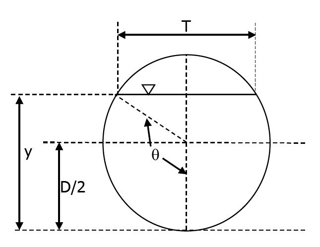
Variables from the figure
- D -- Diameter of original culvert
- T -- Water surface width at critical flow condition
- y -- Depth of flow


