SMS:SRH-2D Coverages 13.0: Difference between revisions
(Created page with "The SRH-2D model makes use of the simulation based modeling approach. This requires defining coverages in the Map module to build the com...") |
No edit summary |
||
| Line 1: | Line 1: | ||
{{SMS Deprecated Feature}} | |||
The SRH-2D model makes use of the simulation based modeling approach. This requires defining [[SMS:Coverages|coverages]] in the [[SMS:Map Module|Map module]] to build the components for use in the SRH-2D [[SMS:Simulations|simulation]]. | The SRH-2D model makes use of the simulation based modeling approach. This requires defining [[SMS:Coverages|coverages]] in the [[SMS:Map Module|Map module]] to build the components for use in the SRH-2D [[SMS:Simulations|simulation]]. | ||
==Boundary Conditions Coverage== | ==Boundary Conditions Coverage== | ||
Latest revision as of 17:25, 5 April 2021
| This contains information about features no longer in use for the current release of SMS. The content may not apply to current versions. |
The SRH-2D model makes use of the simulation based modeling approach. This requires defining coverages in the Map module to build the components for use in the SRH-2D simulation.
Boundary Conditions Coverage
The boundary condition coverage consists of a collection of arcs with specified boundary conditions that control the inflow and outflow in a simulation. The coverage itself has the standard coverage item right-click menu commands as well as two specific commands—the HY-8 Options and BC Types commands. These commands are described below.
HY-8 Options
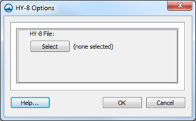
The HY-8 Options command opens the HY-8 Options dialog which allows specifying a link to the location of the HY-8 data file that will be used with this coverage. Only the file name is specified here. If an existing HY-8 file containing culvert crossing attributes already exists, that fie can be selected. Otherwise, a name is specified which will be used when the culvert crossings are defined for this set of boundary conditions. This is an optional parameter and does not need to be filled in unless an HY-8 crossing will be incorporated into the simulation.
BC Types
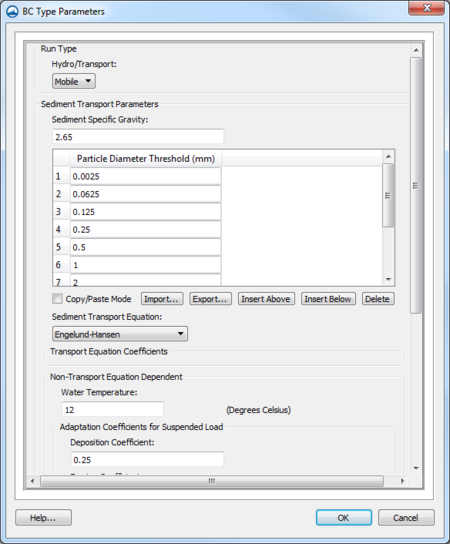
The BC Types command brings up the BC Types Parameters dialog. This dialog supports the run types "Flow" and "Mobile" described below.
Flow Run Type
The "Flow" option is the default and signifies that the SRH-2D simulation will include only hydrodynamic modeling. If this is the desired type of simulation, this parameter does not need to be changed/set. The following options are available:
- Unsteady Output – Can be set to "On" for unsteady flow or "Off" for steady state flow. (This is not recommended.)
Mobile Run Type
The "Mobile" option is used to perform a sediment transport simulation. It should be noted that sediment transport simulations require a hotstart or restart file from a corresponding hydraulic simulation. When the "Mobile" option is specified the dialog expands to include sediment transport parameters.
The sediment transport options are described in the SRH-2D Sediment Transport Parameters article.
Boundary Conditions
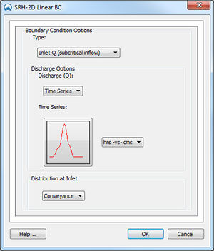
SRH-2D support a variety of boundary conditions for hydraulic computation. The boundary conditions for the model are specified through the SRH-2D Boundary Condition coverage by selecting an arc. In SMS 11.2 and earlier versions a boundary could also be defined by selecting a nodestring in the mesh instead, though this is no longer supported in SMS 12.0 and later versions. Once the arc or nodestring has been selected, double-clicking, or right-clicking and using the Assign Linear BC... command, will bring up a dialog where the boundaries can be assigned.
All currently supported boundary types are exterior boundaries that must be placed on the mesh boundary with the exception of a monitor line. Other boundary types include the following: Inlet-Q, Inlet-SC, Exit-EX, Exit-H, Exit-Q, Wall, and Symmetry.
- Inlet-Q is a subcritical inlet boundary that may be given as a constant discharge or as a variable discharge hydrograph. The velocity distribution type may be selected from the boundary condition menu. Inlet flow volume values can only be positive. For a sediment transport run, the inflowing sediment loads are also specified.
- Inlet-SC is a supercritical inlet boundary that may be given as a constant discharge or as a variable discharge hydrograph. Inlet-SC also requires information about depth. Within the boundary condition menu, the velocity distribution type may be specified. Inlet flow volume values can only be positive. For a sediment transport run, the inflowing sediment loads are also specified.
- Exit-EX is a supercritical exit boundary condition.
- Exit-H is a stage type exit boundary where water surface elevation may be given as a constant number or as a stage-discharge or rating curve. Using a constant or rating curve allows accessing the Populate dialog.
- Exit-Q is an exit boundary with a discharge given as a constant number or as a hydrograph.
- Wall
- Symmetry is defined as a boundary where all dependent variables are extrapolated assuming the gradient of the variable in a direction normal to the boundary is zero except the velocity component normal to the boundary.
- Monitor-Line it is an internal polyline which may be used to monitor the total flow discharge and average water surface elevation. For a sediment transport simulation, the total sediment discharge, concentration, average bed elevation, and sediment discharges by size fraction are added to this output.
- Weir – See the SRH-2D Structures article for more information.
- Culvert – See the SRH-2D Structures article for more information.
- Pressure zone – See the SRH-2D Structures article for more information.
- Gate – See the SRH-2D Structures article for more information.
- Internal Sink – Models a drain or sink inside the model domain.
- Link – Models flow between two separate meshes.
See SRH-2D Boundary Conditions for more information on the options for each boundary type.
Obstructions Coverage
Used to create feature objects that represent obstructions, such as bank protrusions and boulder clusters. Obstructions can be assigned to feature arcs or points.
The elevation that is assigned to the point (for point obstructions) or nodes and vertices (for arc (line) obstructions) will be used as the bottom elevation of the obstruction. If the elevation from node to vertex or vertex to vertex along an arc (line) obstruction is different, the average of the two elevations will be used as the bottom elevation of the obstruction for that "span" of the arc.
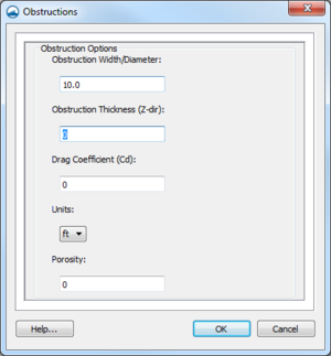
When this coverage is active, double-clicking on a feature arc or point, or right-clicking on an arc or point followed by selecting the Assign Obstructions... command, will bring up the Obstructions dialog.
The Obstructions dialog has the following options:
- Obstruction Width/Diameter – Each arc segment represents a rectangular area based on the assigned width. Each point represents a circular diameter based on the assigned width.
- Obstruction Thickness (Z-dir) – Represents the vertical thickness of the obstruction.
- Drag Coefficient (Cd) – A dimensionless coefficient used to describe the surface upon which the water will be flowing around. See the table below.
- Units – May be assigned to either "ft" (feet) or "m" (meters).
- Porosity – Represents the ability for water to flow through the obstruction object. A porosity of 0 represents a solid surface with no pores allowing for water to pass through the object and 1 represents a surface comparable to a wire mesh with many holes allowing water to pass through it.
| Type of Object | Drag Coefficient | Frontal Area – A |
|---|---|---|
| Long stream-lined body | 0.1 | |
| Hollow semi-sphere facing stream | 0.38 | |
| Solid hemisphere | 0.42 | π / 4 d2 |
| Sphere | 0.5 | |
| Cube | 0.8 | |
| Thin disk | 1.1 | π / 4 d2 |
| Squared flat plate at 90° | 1.17 | |
| Circular cylinder | 1.0–1.3 | |
| Hollow semi-cylinder opposite stream | 1.2 | |
| Long flat plate at 90° | 1.98 |
Monitor Coverage
Monitor points and lines are optional.
If a Monitor coverage has been created, then it must be linked to the SRH-2D simulation. This can be done by dragging the coverage under the simulation item in the Project Explorer or right-clicking on the coverage and using the Link to menu item. When the simulation is launched, monitoring point and line data will be collected and outputted.
In SMS 11.2 only, the Monitor Points coverage must be assigned and selected in the Select the Monitor Point Coverage dialog for SRH-2D to recognize them. The dialog is accessed through the Assign Monitor Points Coverage command in the SRH-2D menu. This process is obsolete in SMS 12.0 and higher.
Starting in SMS version 13.0, monitor lines are no longer set on the Boundary Conditions coverage. Because of this change, when importing SRH-2D projects create in earlier versions of SMS several items will happen:
- SMS will separate the monitoring lines from other arcs in the boundary conditions coverage. The monitoring lines will be placed in their own Monitor coverage.
- The former Boundary Condition coverage will be made into two coverages, one for the monitor lines and the other for the existing boundary conditions. The names of these coverages will have either "Boundary Conditions" or "Monitor" attached to designate which coverage contains the boundary condition arcs and which contains the monitor lines.
- If a Monitor Points coverage existed in the project, this coverage will be changed to a Monitor coverage and the coverage name will have "Monitor" attached.
- If the imported project had both monitor points and monitor lines, their will now be a Monitor coverage for each Monitor Points coverage and a Monitor coverage for each Boundary Condition coverage that contained monitor lines.
- By default, the Monitor coverage with the monitor lines will be included in any simulations.
- The monitor points and monitor lines from the previous project will need to be merged into one Monitor coverage and linked to the simulation in order for both points and lines to be included in the simulation run.
- The default boundary condition for arcs on an SRH-2D boundary condition coverage is now the "Wall" type. The boundary condition arcs should be reviewed to ensure no parameters were lost in the conversion.
Monitor Points
If choosing to have monitor points, add points using the Create Feature Point tool in the Monitor coverage. A monitor point is used to gather specific information for that location at all time steps. Information calculated by SRH-2D at a monitor point includes position in the X and Y direction, bed elevation, water elevation, water depth, X direction velocity component, Y direction velocity component, velocity magnitude, Froude number, and shear stress. This data is written to a separate output file for each monitor point. These files appear in the output directory and are called PT(n).dat, where n is a sequential integer corresponding to the order of the SMS feature point ID numbers for the monitor points.
To ensure the ID number will match the numbers appended to the data files, it is recommended that the following be done:
- Create all monitor points before creating monitor lines.
- Renumber the Monitor coverage before running SRH-2D.
For a sediment transport simulation, the D50 particle size is included in the monitor point output file, and an additional sediment monitor point file is created that includes concentration, erosion and deposition, and bed material gradations.
Usually, one monitor point will be created near the outflow boundary and another near the inflow or perhaps near an area of interest. Water levels for the first two monitor points created will be displayed during the model run.
Monitor Lines
Monitor Lines are created to extract data from the solution along an arc. Monitor lines are optional, but highly recommended to help verify continuity and model stability. SRH-2D will calculate the total flow across the arc and the average water surface elevation along the arc.
Create monitor lines using the Create Feature Arc tool, and digitizing arcs in the Monitor coverage. Create the arcs in the Monitor coverage at locations where it is desirable to compute flow. The direction of the monitor line does not matter, except that flow values will be reported as positive or negative if the line creation direction is reversed. It is recommended that monitor lines be created near the inflow and outflow boundaries. Monitor lines must be created inside the domain and not outside the domain or on the edge of the domain. Monitoring flows near the outflow boundary can help verify model continuity. Monitor lines are also useful for evaluating flow splits or other areas where the flow across a line is desirable.
Monitor line output is written to a separate output file for each monitor line. These files will appear in the output directory and are called LN(n).dat, where n is a sequential integer corresponding to the order of the SMS feature arc ID numbers. The monitor lines are save sequentially from how they are encountered in by the SRH-2D model run. Displaying the ID numbers in the Monitor coverage will show the order.
To ensure the ID number will match the numbers appended to the data files, it is recommended that the following be done:
- Create all monitor points before creating monitor lines.
- Renumber the Monitor coverage before running SRH-2D.
Once steady state is achieved, flows reported in these files corresponding to monitor lines placed near the outflow should be very close to the total inflow. Also, reviewing the flow and WSE values reported in these files at the final time steps can help verify model stability. Unstable models may show varying or oscillating values for the flows reported for the monitor line.
Materials Coverage
The SRH-2D materials coverage allows creating material zones specific to the SRH-2D model. The materials zones must cover the domain extents of the project.
Materials Coverage Right-Click Menu
The materials coverage has the standard coverage item right-click menu commands as well as specific right-click commands. The following commands are also part of the SRH-2D materials coverage:
- Material Properties – Opens the Material Properties dialog.
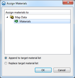
- Assign Material To – Opens the Assign Materials dialog for managing multiple material coverages.
Assign Materials
SRH-2D allows the option to have multiple material coverages. When multiple material coverages exist, there are options to manage these coverages. By right-clicking on an SRH-2D materials coverage and selecting the Assign Materials to... command, the Assign Materials dialog can be accessed. This dialog allows adding the unique material definition of one material coverage to that of another material coverage. Select the target material coverage that will be modified by the material coverage used to access the dialog. There are then two option for how SMS will modify the target material coverage.
- Append to target material list – This will add any unique material definitions to the target material coverage.
- Replace target material list – Deletes the existing material definitions in the target material coverage and replaces them with the selected material coverage.
After performing either of these actions, opening the Material Properties dialog for the target material coverage will show the material list modified with the new definitions.
Assigning Materials to Polygons
Materials can be assigned to individual polygons using the Select Polygon tool and double-clicking on a polygon in the materials coverage. This will bring up the Assign Material Properties dialog.
The Assign Material Properties dialog can also be reached by right-clicking on a polygon in the materials coverage and selecting the Assign Material Properties command.
See SRH-2D Material Properties for more information about the Assign Material Properties dialog.
Sediment Materials Coverage
The SRH-2D Sediment Materials coverage is similar to the Materials coverage, however, the materials zones in this coverage assign sediment properties. The coverage has the same right-click menu options as the Materials coverage.
Sediment materials are assigned to polygons. The polygons are then "snapped" to the mesh elements during the model run. If the border of a polygon falls on the centroid of an elementa, it will be unassigned. If this happens, SMS will give a warning when launching the simulation. This warning can be ignored in some cases, such as when the cell is a fringe cell or when cells are intentionally disabled, but this is up to the user's discretion.
Sediment layer thicknesses, gradations, and bulk densities (in dry unit weights in lb/ft3 or kg/m3) are provided for each layer. A non-erodible material can be specified by leaving the layer information blank.
For more information, see the Sediment Material Properties article.
Related Topics
SMS – Surface-water Modeling System | ||
|---|---|---|
| Modules: | 1D Grid • Cartesian Grid • Curvilinear Grid • GIS • Map • Mesh • Particle • Quadtree • Raster • Scatter • UGrid |  |
| General Models: | 3D Structure • FVCOM • Generic • PTM | |
| Coastal Models: | ADCIRC • BOUSS-2D • CGWAVE • CMS-Flow • CMS-Wave • GenCade • STWAVE • WAM | |
| Riverine/Estuarine Models: | AdH • HEC-RAS • HYDRO AS-2D • RMA2 • RMA4 • SRH-2D • TUFLOW • TUFLOW FV | |
| Aquaveo • SMS Tutorials • SMS Workflows | ||
