User:Kczappa: Difference between revisions
No edit summary |
No edit summary |
||
| Line 1: | Line 1: | ||
'''Kayla Czappa''' | '''Kayla Czappa''' | ||
CityWater Model Runs | |||
When performing model runs with CityWater, it is common to see a lag in the amount of time it takes to process the run. When there are too many runs to perform simultaneously, CityWater uses a scheduling system to sort the model runs. To ensure that each product can get processed effectively without crashing, CityWater was designed to organize each run into a waiting queue which can be the cause of longer run times for the runs. | |||
Another reason the run times can be longer, is due to a number of things. | |||
1. Writing the results to the database – CityWater is must be able to access the results. Therefore, some of the time used to execute the run goes towards writing the results to the database so that the CityWater app can find and access the data that is needed. | |||
2. Performing extra analysis – One of the reasons it takes CityWater longer to run than in Epanet is because CityWater has to generate the zone, pressure swing, and peak-day fire flow layers which aren't offered in Epanet. | |||
3. Generating the visualization layers – CityWater uses visualization layers to display the model on the map which takes more time to generate which leads to a longer run time. | |||
Running Scenarios | |||
Since not all of the steps above are necessary while running scenarios, it is more common for a scenario to run faster than the initial upload. Running the scenario, however should take roughly the same amount of time as it would for the initial model upload. Both the number of pipes and the number of time steps contained within the model will increase the amount of time it takes to run the model, because the size of the model increases accordingly. The suggested amount of pipes for a given project is roughly around 10,000 – 15,000 pipes and 100 time steps since, at this time, CityWater best performs under these parameters. | |||
Ways to better the outcome of larger scale models include: | |||
1. Reducing the number of pipes – An accurate Epanet model is not always contingent on a high number of pipes. Therefore, it is likely that reducing the pipes | |||
Revision as of 21:06, 2 June 2020
Kayla Czappa
CityWater Model Runs
When performing model runs with CityWater, it is common to see a lag in the amount of time it takes to process the run. When there are too many runs to perform simultaneously, CityWater uses a scheduling system to sort the model runs. To ensure that each product can get processed effectively without crashing, CityWater was designed to organize each run into a waiting queue which can be the cause of longer run times for the runs.
Another reason the run times can be longer, is due to a number of things.
1. Writing the results to the database – CityWater is must be able to access the results. Therefore, some of the time used to execute the run goes towards writing the results to the database so that the CityWater app can find and access the data that is needed.
2. Performing extra analysis – One of the reasons it takes CityWater longer to run than in Epanet is because CityWater has to generate the zone, pressure swing, and peak-day fire flow layers which aren't offered in Epanet.
3. Generating the visualization layers – CityWater uses visualization layers to display the model on the map which takes more time to generate which leads to a longer run time.
Running Scenarios
Since not all of the steps above are necessary while running scenarios, it is more common for a scenario to run faster than the initial upload. Running the scenario, however should take roughly the same amount of time as it would for the initial model upload. Both the number of pipes and the number of time steps contained within the model will increase the amount of time it takes to run the model, because the size of the model increases accordingly. The suggested amount of pipes for a given project is roughly around 10,000 – 15,000 pipes and 100 time steps since, at this time, CityWater best performs under these parameters.
Ways to better the outcome of larger scale models include:
1. Reducing the number of pipes – An accurate Epanet model is not always contingent on a high number of pipes. Therefore, it is likely that reducing the pipes
Links to finish:
https://www.xmswiki.com/wiki/WMS:Assigning_an_Equation#Basin_Time_Computation_Dialog (REcent)
https://www.xmswiki.com/wiki/WMS:File_Import_Wizard#Step_1_.E2.80.93_File_Outline
Links to remember to edit:
Pages On WMS that needs to be done:
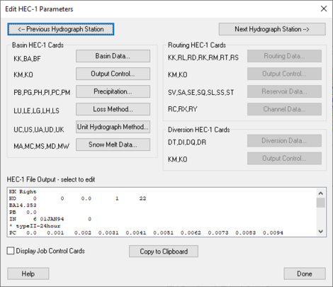
Edit HEC-1 Parameters Dialog which include:
Basin HEC-1 Cards dialogs that include:
Basin Data... Output Control... Precipitation... Loss Method... Unit Hydrograph Method... Snow Melt Data...
Routing HEC-1 Cards dialogs include:
Routing Data... Output Control... Reservoir Data... Channel Data... Output Control...
HEC-1 File Output (select to edit)
WMS: Edit HEC-1 Parameters dialog
When a basin is selected in the HEC-1 model, selecting HEC-1 | Edit Parameters will bring up the Edit HEC-1 Parameters dialog with the Basin HEC-1 Cards section active. The following can then be specified:
<--Previous Hydrograph Station –
Next Hydrograph Station--> –
Basin HEC-1 Cards section –
- Basin Data... – Allows the specification of Basin Data.
- KK – Basin Name.
- BA – Basin Area.
- BF – Baseflow.
- Output Control... – Allows different output controls to be specified.
- KM – Comment Lines.
- KO – Output Control.
- Precipitation... – Allows the specification of precipitation data.
- PB – Basin Average Precipitation.
- PG – Precipitation Gage.
- PH – Hypothetical Storm.
- PI – Probable Maximum Precipitation.
- PC –
- PM –
- Loss Method... – Allows the specification of Loss Methods being applied.
- LU – Uniform Loss Method.
- LE – Exponential Loss
- LG – Green & Ampt.
- LH – Holtan.
- LS – SCS Loss Method.
- Unit Hydrograph Method... – Allows the specification of Hydrograph methods being applied.
- UC – Clark Unit Hydrograph.
- US – Snyder
- UA –
- UD – SCS Dimensionless.
- UK – Kinematic Wave.
- Snow Melt Data... – Allows the specification of snow melt data.
- MA – Elevation Zone Data.
- MC –
- MS – Shot-Wave Radiation Time Series.
- MD – Dew Point Time Series.
- MW – Wind Speed Time Series.
Routing HEC-1 Cards section –
- Routing Data... – Allows the specification of routing data.
- KK – Outlet Names.
- RL – Channel Losses.
- RD – Muskingum-Cunge.
- RK – Kinematic Wave.
- RM – Muskingum.
- RT – Straddler Stagger.
- RS – Storage Routing.
- Output Control... – Allows different output controls to be specified.
- KM – Comment Lines.
- KO – Output Control.
- Reservoir Data... – Allows the specification of reservoir data.
- SV – Volume.
- SA – Area.
- SE – Elevation.
- SQ – Outflow.
- SL – Low-Level Outlet.
- SS – Spillway Characteristics.
- ST – Dam Overtopping.
- Channel Data... – Allows the specification of Channel data.
- AC –
- RX –
- RY –
Diversion HEC-1 Cards section –
- Diversion Data... – Allows the specification of diversion data.
- DT – Editing Diversion Data.
- DI – Inflow.
- DQ – Outflow.
- DR –
- Output Control... – Allows different output controls to be specified.
- KM – Comment Lines.
- KO – Output Control.
HEC-1 File Output-select to edit section –
"Display Job Control Cards" – By selecting this, it allows the Job Controls to be viewed.
Copy to Clipboard – Allows the information to be copied to the clipboard for any future use.
Help –
Channel Data Dialog
RK/RD Channels Dialog
Accessed by selecting Define Channels in the Kinematic wave section of the HEC-1 Unit Hydrograph Methods dialog. Main Channel RK/RD record
- Normal Muskingum Cunge Parameters
- L – Channel length.
- S – Channel slope.
- N – Manning's roughness.
- Shape – Characteristic channel shape.
- TRAP – Trapezoid.
- DEEP – Deep.
- CIRCULAR – Circular.
- WD – Base width of the channel.
- Z – Side slope of channel.
- Use Cross Section – Select to bring up the Define Cross Section option in this dialog.
- Define Cross Section – Select to bring up the XY Series Editor dialog.
Second RK/RD record (HMS collector) – Select to enter a second RK/RD record.
- L – Channel length.
- S – Channel slope.
- N – Manning's roughness.
- Shape – Characteristic channel shape.
- TRAP – Trapezoid.
- DEEP – Deep.
- CIRCULAR – Circular
- WD – Base width of the channel.
- Z – Side slope of channel.
Third RK/RD record (HMS collector) – Select to enter a third RK/RD record.
- L – Channel length.
- S – Channel slope.
- N – Manning's roughness.
- Shape – Characteristic channel shape.
- TRAP – Trapezoid.
- DEEP – Deep.
- CIRCULAR – Circular.
- WD – Base width of the channel.
- Z – Side slope of channel.
Route upstream hydrographs to main channel – Select to route upstream hydrographs to the main channel.
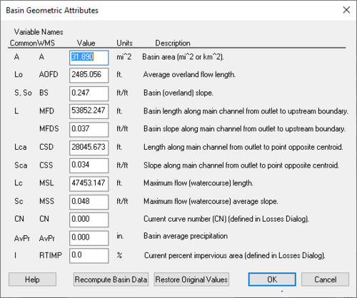
WMS:Basin Geometric Attributes Dialog
Accessed by selecting Basin Geometrical Attributes located in the HEC-1 Unit Hydrograph Methods dialog. Variable Names – Below the Variable Names heading is a table that allows the inputting of values for each one of the listed variables' names.
Recompute Basin Data – Select to bring up the Units dialog.
Restore Original Values – Select to revert all values in the Variable Names table back to their original values.
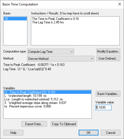
Basin Time Computation DONE Dialog
Accessed by selecting Compute Parameters-Basin Data in the HEC-1 Unit Hydrograph Methods dialog. Basin – Instructions / Results (You may have to scroll down) – Computational type: –
| Selections | Selection Options | ||
|---|---|---|---|
| Method: | "Denver Method"
"Tulsa Rural Method" – "Tulsa 50% Urban Method" – "Tulsa 100% Urban Method" – "Espey Rural Method" "Espey No Urbanization Method" "Espey Partly Urban Method" "Espey Completely Urban Method" "Riverside Mountains Method" "Riverside Foothills Method" "Eagleson Method" "USGS Nationwide Urban Method" "Putnam Method" "Taylor Method" "Colorado State University (CSU) Method" "Scs Method" "Custom Method" | ||
| User Defined... – | Select to bring up Modify Equation dialog. | ||
| Modify Equation... | Select to bring up the Modify Equation dialog that allows you to modify the equation used for the Basin time computation. | ||
| Basin Variables... – | Select to open the Basin Geometric Attributes dialog. |
| Selections | Selection Options | ||
|---|---|---|---|
| Method: | "User Defined Method"
"Kirpich Method for overland flow on bare earth" "Kirpich Method for overland flow on grassy earth" "Kirpich Method for overland flow on asphalt" "Kirpich Method for overland flow on bare earth (Mountains)" "Kirpich Method for overland flow on grassy earth (Mountains)" "Kirpich Method for overland flow on asphalt (Mountains)" "Ramser Method for channel flow" "Fort Bend County Method" "Kerby Method for overland flow" "ADOT Method (Desert/Mountain)" "ADOT Method (Urban)" | ||
| User Defined... – | Select to bring up Modify Equation dialog. | ||
| Modify Equation... | Select to bring up the Modify Equation dialog that allows you to modify the equation used for the Basin time computation. | ||
| Basin Variables... – | Select to open the Basin Geometric Attributes dialog. |
- Instructions – Place that allows the reading of warnings that may occur in the equation as well as a list of pre-defined variables that are computed by WMS.
Equation – The equation being used for calculation.
- Parse – Click to parse through the equation.
Variable Abbreviations – A list of variable abbreviations relating to the equation. Definitions – A list of definitions for the variable abbreviations. Units – ||The units that apply to the definition chosen.
- "none"
- "ft"
- "m"
- "km"
- "mi"
- hr"
- "min"
- "sec"
- "sq. mi"
- "sq. km"
- "sq. ft"
- "acre"
- "hect"
- "in"
- "mm"
- "ft/mi"
- "fract"
Method:
Related links: https://www.xmswiki.com/wiki/WMS:Travel_Times_from_Basin_Data
https://www.xmswiki.com/wiki/WMS:Denver_Lag_Time_Equation
estimation of the channel velocity measured in feet per second.
Define Reservoir Data – Select to open Define Reservoir Data dialog.
Related Links:
https://www.xmswiki.com/wiki/WMS:TR-20_Reservoir_Data
Reservoir Output Control – Select to open Reservoir Output Control dialog.
Related Links:
https://www.xmswiki.com/wiki/WMS:TR-20_Reservoir_Data
Editing HY8:Controlling Plot Display Options
https://www.xmswiki.com/index.php?title=HY8:Controlling_Plot_Display_Options&action=edit


