WMS:TIN Guidelines
TINs are formed by connecting a set of XYZ points (scattered or gridded) with edges to form a network of triangles. Points used to create TINs can be obtained by digitizing a contour map (or a scanned image inside of WMS), by generated automatically from feature arcs and polygons, or by using DEMs or existing TINs as background elevation maps. TINs can be contoured, displayed in oblique view with mapped images and hidden surfaces removed, and have several other display options that can be set to visualize and understand the terrain surface better. TINs should primarily be used for elevation data conversion, merging various elevation sources, creating DEMs, and extracting cross-sections and other data for hydrologic models. The WMS developers recommend using DEMs for hydrologic modeling. Hydrologic modeling using DEMs is simpler and more robust than hydrologic modeling using DEMs.
However, TINs can be used for basin delineation and drainage analysis. Basin areas and several other geometric parameters can be computed and combined with hydrologic analyses. This section focuses on steps that can be used to process TINs for watershed delineation, but some of the features described here can also be useful for other needs.
The Project Explorer can be used to set the name of the TIN by either double-clicking on the TIN name, or by right-clicking on the name and choosing Rename. The name of the TIN is always displayed along with the TIN icon when using the Select TIN tool.
Developing watersheds from TINs often involves the use of both feature objects and DEMs. The following steps can be used as a guideline for watershed characterization with TINs.
1. Obtain Background Elevation
An elevation source is required for creating a TIN. Even if there is already a TIN data source, it's recommended that in most cases to use it as a background elevation source and create a new TIN from it. A background elevation source can be a DEM, TIN, or both.
2. Smooth the Background Elevation
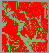
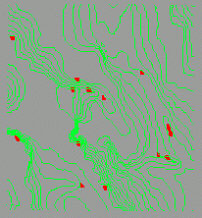
Digital elevation data are often rounded to the nearest integral value (foot or meter) for storage efficiency. However, this can cause problems for automated basin delineation techniques, especially where there is relatively little relief. WMS has utilities for smoothing both DEM and TIN background elevation data. The results can be dramatic as seen in the set of figures below, and often make the difference in being able to successfully complete a watershed modeling project.
3. Create a Conceptual Model with Feature Objects
In order to ensure that triangle edges in the resulting TIN will conform to streams and other important drainage features, identify them with feature objects. A rough basin boundary defining the domain of the TIN region needs to be created. Additionally, any lines such as streams and roads that should be represented with triangle edges should also be created as part of the conceptual model.
Conceptual models can be created in many different ways, but some of the easiest ways in WMS include:
- Import existing digital data in GIS, CAD (DXF), DLG, or other simplified XY formats.
- Use a contour display of a DEM and on-screen digitize the rough boundary and stream arcs.
- Use a registered image as a background for on-screen digitizing.
- Use a DEM to define flow accumulations and then convert to stream arcs as described in step five of the previous section.
- Use a hillshaded DEM image as a background for on-screen digitizing. The Screen Capture command in the Images menu can be useful for saving a hillshaded DEM as an image file.
4. Redistribute Vertices
The density of vertices in the TIN created from the conceptual model and background elevation data can be controlled by the spacing of arc vertices in the conceptual model. WMS has tools to automatically increase or decrease arc vertex density. The density may vary along the arcs, allowing for higher definition in some regions and lower in others.
5. Create TIN
TIN creation builds on the previous four steps. The outer polygon is used to define the limits or extents of the TIN. TIN vertices are created inside this polygon at a density proportional to the spacing of vertices on the nearest arc. After the TIN is created, the stream (and other interiors) arcs are forced as breaklines so that they are honored in the TIN as triangle edges, and the elevations for the vertices are interpolated from the background elevation map.
6. Edit TIN
Even though the newly created TIN conforms to the topographic features defined by feature arcs, there are inevitably some anomalies that must be corrected in order to use the TIN for basin delineation. These include flat triangles, flat edges, and pits. WMS contains several tools for both automatic and manual (user interaction) elimination of these anomalies.
7. Complete Stream Network and Outlet Definitions
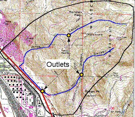
By default there may only be a single outlet point for the watershed defined, or perhaps only a portion of the stream network. WMS can be used to add additional outlet points (representing sub-basin outlets, culverts, etc.) and stream branches after the TIN has been created from the feature objects. Even after delineation, it is possible to return to this step and redefine the locations where sub-basins are to be created.
8. Delineate Basins
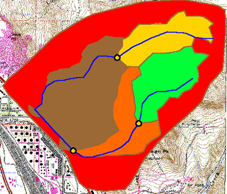
A flow path is initiated from the centroid of each triangle and followed until the first outlet point. The triangle is then assigned the basin ID corresponding to the branch of the stream the flow path entered from (by default, a separate basin is created for each upstream branch of an outlet). Basins can be merged later, providing they both belong to the same outlet point.
9. Refine TIN
During the basin delineation process in step eight some problems with divergent or splitting flow paths may occur. Again, WMS has tools which will allow correcting these problems automatically and manually. The automatic method will correct the problem about 90% of the time, while in 10% of the cases it may be necessary to swap edges or edit the TIN in some other way in order to eliminate the split flow vertices.
If there are no split-flow vertices, or after having corrected them, refine the boundaries and then eliminate triangles exterior to the actual watershed. Triangle basins are defined based on flow paths from the centroid of the triangle, so some triangles will actually straddle the basin boundary. The Refine Boundaries command of the TIN menu will split these triangles along the true boundary and results in "smoother" basin boundaries. Once satisfied with the watershed boundary, the Delete Null Basin Triangles command is used to eliminate all triangles whose flow paths do not pass through an outlet (basin).
10. Compute Basin and Stream Parameters
With the stream network and basin boundaries defined, several important geometric parameters can be computed. These parameters (area, slope, length, etc.) are automatically tied to the hydrologic models (HEC-1, TR-20, etc.) where appropriate.
11. Define the Hydrologic Model
Along with the watershed definition on the TIN, an accompanying topologic model is created. Then interact with the TIN or tree representation of the watershed to complete input for and run the supported hydrologic models.
Related Topics
WMS – Watershed Modeling System | ||
|---|---|---|
| Modules: | Terrain Data • Drainage • Map • Hydrologic Modeling • River • GIS • 2D Grid • 2D Scatter |  |
| Models: | CE-QUAL-W2 • GSSHA • HEC-1 • HEC-HMS • HEC-RAS • HSPF • MODRAT • NSS • OC Hydrograph • OC Rational • Rational • River Tools • Storm Drain • SMPDBK • SWMM • TR-20 • TR-55 | |
| Toolbars: | Modules • Macros • Units • Digitize • Static Tools • Dynamic Tools • Drawing • Get Data Tools | |
| Aquaveo | ||


