HY8:Hook Basin
From XMS Wiki
(Redirected from HY-8:Hook Basin)
Jump to navigationJump to search
Hook Basin
The input variables required for this calculation is the following:
- Shape of Dissipator — The user can select 'Warped Wingwalls' or 'Trapezoidal'. See illustrations below for examples.
- Flare Angle (Warped Wingwalls only) — Flare angle per side of the basin.
- Ratio of Length to A-hooks over Total Basin Length (Warped Wingwalls only) — Distance from culvert exit to first row of hooks (A-HOOKS) divided by the total length of the basin.
- Ratio of Width to A-hooks over Total Basin Length (Warped Wingwalls only) — Distance between hooks in the first row divided by the basin width at the first row.
- Ratio of Length to B-Hooks over Total Basin Length (Warped Wingwalls only) — Distance from culvert exit to second row of hooks (B-HOOKS) divided by the total length of the basin.
- Width for the Downstream End of the Basin (Warped Wingwalls only)
- Basin Side Slope (Trapezoidal shape only) — The user can select either '1.5 : 1' or '2 : 1'.
- Basin Bottom Width (Trapezoidal shape only)
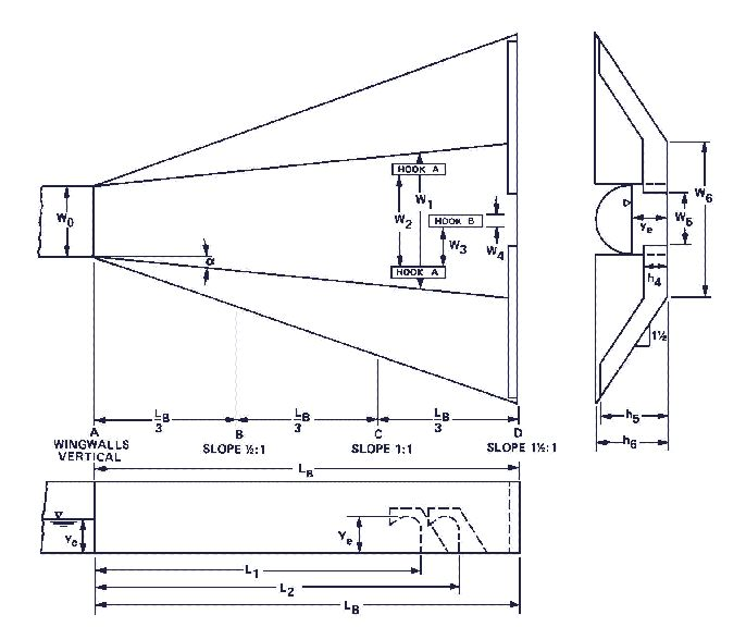
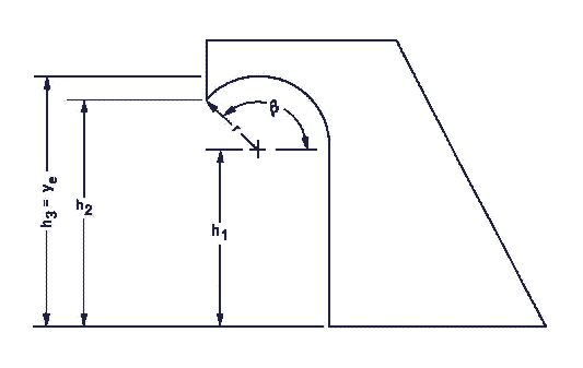
The next two figures show a hook basin with warped wingwalls:
Variables from the figure
- W0 — Outlet width
- W1 — Width at first hooks
- W2 — Distance between first hooks (row A)
- W3 — lateral spacing between A and B hook
- W4 — Width of hooks
- W5 — Width of slot in end sill
- W6 — approximately channel width
- h4 — Height of end sill
- h5 — Height to top of end sill
- h6 — Height to top of warped wingwall
- ye — Equivalent depth
- L1 — Distance to first hooks
- L2 — Distance to second hooks (row B)
- LB — Basin length
Variables from the figure
- ß — Angle of radius
- r — radius
- h1 — height to center of radius
- h2 — Height to point
- h3 — Height to top of radius
- ye — Equivalent depth
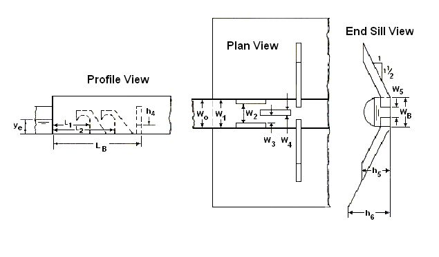
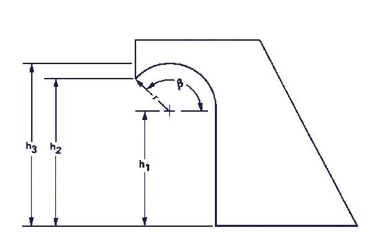
The next two figures show a hook basin with a uniform uniform trapezoidal channel:
Variables from the figure
- W0 — Outlet width
- W1 — Width at first hooks
- W2 — Distance between first hooks (row A)
- W3 — lateral spacing between A and B hook
- W4 — Width of hooks
- W5 — Width of slot in end sill
- WB — approximately channel width
- h4 — Height of end sill
- h5 — Height to top of end sill
- h6 — Height to top of warped wingwall
- ye — Equivalent depth
- L1 — Distance to first hooks
- L2 — Distance to second hooks (row B)
- LB — Basin length
Variables from the figure
- ß — Angle of radius
- r — radius
- h1 — height to center of radius
- h2 — Height to point
- h3 — Height to top of radius


