(
diff)
← Older revision | Approved revision (diff) | Latest revision (diff) | Newer revision → (diff)
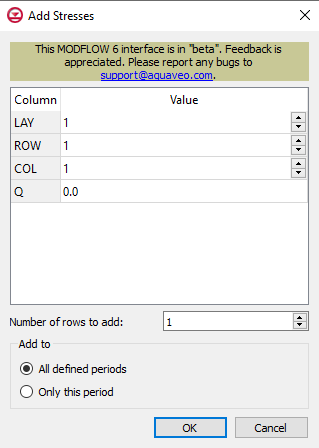
Add Stresses Dialog
The
Add Stresses dialog for the HFB package
The Add Stresses dialog is accessed by clicking Add Rows  in the Periods section of several MODFLOW 6 package dialogs. It contains the following sections and options:
- Table – Table Options differ according to each package. See chart below.
- Number of rows to add – Use the Increment Up and Down
 buttons to select the desired number of rows to add.
- Add to section – Radio buttons with the following options:
- All defined periods – Select to add the rows to all defined periods.
- Only this period – Select to add the rows to only this period.
| Package
|
Add Stresses Dialog Table Options
|
| CHD
|
| CHD Options
|
- LAY – Used to specify certain layers.
- ROW – Used to specify certain rows.
- COL – Used to specify certain columns.
- HEAD – Represents the head at the boundary.
|
|
| DRN
|
| DRN Options
|
- LAY – Used to specify which layer is being applied.
- ROW – Used to specify which row is being applied.
- COL – Used to specify which column is being applied.
- ELEV – Represents the elevation of the drain.
- COND – Represents the hydraulic conductance between the aquifer and the drain.
|
|
| GHB
|
| GHB Options
|
- LAY – Used to specify certain layers of the module.
- ROW – Used to specify which row is being applied.
- COL – Used to specify which column is being applied.
- BHEAD – Represents the boundary head.
- COND – Represents the hydraulic conductance between the aquifer cell and the boundary.
|
|
| HFB
|
| HFB Options
|
- LAY1 – Represents the first of two chosen layers.
- ROW1 – Represents the first of two chosen rows.
- COL1 – Represents the first of two chosen columns.
- LAY2 – Represents the second of two chosen layers.
- ROW2 – Represents the second of two chosen rows.
- COL2 – Represents the second of two chosen columns.
- HYDCHR – The hydraulic characteristic of the horizontal-flow barrier. When this variable is negative it multiplied by the conductance of two cells.
|
|
| LAK
|
| LAK Options
|
- LAKENO_OUTLETNO – A value that defines the reach number associated with the specified PERIOD data.
- SETTING – Information that is linked to keywords and values.
- VALUE1 – Value to be entered in relation to the specific project.
- VALUE2 – Value to be entered in relation to the specific project.
|
|
| MAW
|
| MAW Options
|
- WELLNO – A value that defines the reach number associated with the specified PERIOD data.
- MAWSETTING – Information that is linked to keywords and values.
- VALUE1 – Value to be entered in relation to the specific project.
- VALUE2 – Value to be entered in relation to the specific project.
- VALUE3 – Value to be entered in relation to the specific project.
|
|
| RIV
|
| RIV Options
|
- LAY – Used to specify which row is being applied.
- ROW – Used to specify which row is being applied.
- COL – Used to specify which column is being applied.
- STAGE – Variable that represents the head in the river.
- COND – Variable that represents the riverbed hydraulic conductance.
- RBOT – Variable that represents the elevation of the bottom of the riverbed.
|
|
| SFR
|
| SFR Options
|
- RNO – A value that defines the reach number associated with the specified PERIOD data.
- SFRSETTING – Information that is linked to keywords and values.
- VALUE1 – Value to be entered in relation to the specific project.
- VALUE2 – Value to be entered in relation to the specific project.
|
|
| UZF
|
| UZF Options
|
- IUZNO – An integer value that defines the UZF cell number associated with the specified PERIOD data on the line.
- FINF – A value that defines the applied infiltration rate of the UZF cell.
- PET – A value that defines the ET rate of the UZF cell and specified GWF cell.
- EXDP – A value that defines the ET extinction depth of the UZF cell.
- EXTWC – A value that defines the amount of water removed from the UZF cell through evapotranspiration.
- HA – A value that defines the amount of potential air that enters the UZF cell.
- HROOT – A value that defines the root potential of the UZF cell.
- ROOTACT – A value that defines how much root activity exists in the UZF cell.
|
|
| WEL
|
| WEL Options
|
- LAY – Represents which layer within the grid to which the chosen well will be assigned.
- ROW – Represents which row within the grid to which the chosen well will be assigned.
- COL – Represents which column within the grid to which the chosen well will be assigned.
- Q – Represents the volumetric well rate at which the recharge (positive value) and discharge (negative value) of the well will be.
|
|
