From XMS Wiki
This is the approved revision of this page, as well as being the most recent.
Jump to navigationJump to search
Add Stresses Dialog
The
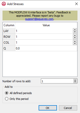
Add Stresses dialog for the HFB package
The Add Stresses dialog is accessed by clicking Add Rows  in the Periods section of several MODFLOW 6 package dialogs. It contains the following sections and options:
- Table – Table Options differ according to each package. See chart below.
- Number of rows to add – Use the Increment Up and Down
 buttons to select the desired number of rows to add.
- Add to section – Radio buttons with the following options:
- All defined periods – Select to add the rows to all defined periods.
- Only this period – Select to add the rows to only this period.
| Package
|
Add Stresses Dialog Table Options
|
| CHD
|
| CHD Options
|
- LAY – Used to specify certain layers.
- ROW – Used to specify certain rows.
- COL – Used to specify certain columns.
- HEAD – Represents the head at the boundary.
|
|
| DRN
|
| DRN Options
|
- LAY – Used to specify which layer is being applied.
- ROW – Used to specify which row is being applied.
- COL – Used to specify which column is being applied.
- ELEV – Represents the elevation of the drain.
- COND – Represents the hydraulic conductance between the aquifer and the drain.
|
|
| GHB
|
| GHB Options
|
- LAY – Used to specify certain layers of the module.
- ROW – Used to specify which row is being applied.
- COL – Used to specify which column is being applied.
- BHEAD – Represents the boundary head.
- COND – Represents the hydraulic conductance between the aquifer cell and the boundary.
|
|
| HFB
|
| HFB Options
|
- LAY1 – Represents the first of two chosen layers.
- ROW1 – Represents the first of two chosen rows.
- COL1 – Represents the first of two chosen columns.
- LAY2 – Represents the second of two chosen layers.
- ROW2 – Represents the second of two chosen rows.
- COL2 – Represents the second of two chosen columns.
- HYDCHR – The hydraulic characteristic of the horizontal-flow barrier. When this variable is negative it multiplied by the conductance of two cells.
|
|
| LAK
|
| LAK Options
|
- LAKENO_OUTLETNO – A value that defines the reach number associated with the specified PERIOD data.
- SETTING – Information that is linked to keywords and values.
- VALUE1 – Value to be entered in relation to the specific project.
- VALUE2 – Value to be entered in relation to the specific project.
|
|
| MAW
|
| MAW Options
|
- WELLNO – A value that defines the reach number associated with the specified PERIOD data.
- MAWSETTING – Information that is linked to keywords and values.
- VALUE1 – Value to be entered in relation to the specific project.
- VALUE2 – Value to be entered in relation to the specific project.
- VALUE3 – Value to be entered in relation to the specific project.
|
|
| RIV
|
| RIV Options
|
- LAY – Used to specify which row is being applied.
- ROW – Used to specify which row is being applied.
- COL – Used to specify which column is being applied.
- STAGE – Variable that represents the head in the river.
- COND – Variable that represents the riverbed hydraulic conductance.
- RBOT – Variable that represents the elevation of the bottom of the riverbed.
|
|
| SFR
|
| SFR Options
|
- RNO – A value that defines the reach number associated with the specified PERIOD data.
- SFRSETTING – Information that is linked to keywords and values.
- VALUE1 – Value to be entered in relation to the specific project.
- VALUE2 – Value to be entered in relation to the specific project.
|
|
| UZF
|
| UZF Options
|
- IUZNO – An integer value that defines the UZF cell number associated with the specified PERIOD data on the line.
- FINF – A value that defines the applied infiltration rate of the UZF cell.
- PET – A value that defines the ET rate of the UZF cell and specified GWF cell.
- EXDP – A value that defines the ET extinction depth of the UZF cell.
- EXTWC – A value that defines the amount of water removed from the UZF cell through evapotranspiration.
- HA – A value that defines the amount of potential air that enters the UZF cell.
- HROOT – A value that defines the root potential of the UZF cell.
- ROOTACT – A value that defines how much root activity exists in the UZF cell.
|
|
| WEL
|
| WEL Options
|
- LAY – Represents which layer within the grid to which the chosen well will be assigned.
- ROW – Represents which row within the grid to which the chosen well will be assigned.
- COL – Represents which column within the grid to which the chosen well will be assigned.
- Q – Represents the volumetric well rate at which the recharge (positive value) and discharge (negative value) of the well will be.
|
|
