Template:Bridge Footprint Tool
Bridge Footprint
The Bridge Footprint tool can be used to assist in the creation of an unstructured mesh under and around a bridge structure. Meshing this portion of a domain can lead to complexity. By the nature of the region, flow is complex due to contractions, obstructions and local flow patterns around piers and abutments. When water levels are high enough to induce pressure flow, the constraints on meshing are even more critical.
Some models, such as SRH-2D are more stable when the elements just upstream and downstream of the transitions into and out of pressure flow are rectangular elements aligned to the flow. Further, wrapping structures such as piers with small elements transitioning to larger elements has traditionally required many polygons in a Mesh Generation coverage.
The Bridge Footprint tool requires a definition of a bridge footprint to be provided generically in any coverage type. This definition consists of:
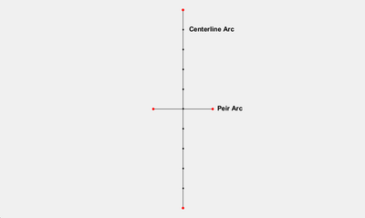
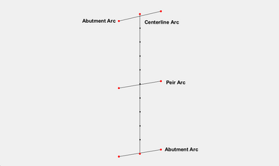
- An arc along the centerline of the bridge. The distribution of vertices on the centerline affects the number of elements created.
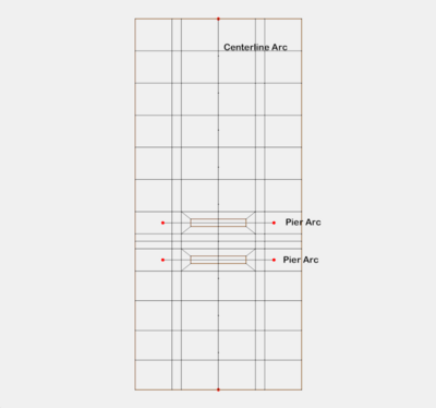
- Arcs crossing the centerline (but not intersecting at a node) at the location of each pier (wall pier or pier group).
- Arcs crossing the centerline near the end defining the orientation of the bridge abutments if these abutments are not perpendicular to the centerline.
The tool creates a coverage that bounds the area of the bridge that can be incorporated into a Mesh Generation coverage of the simulation domain along with a mesh that represents the area under and around the bridge.
Input parameters
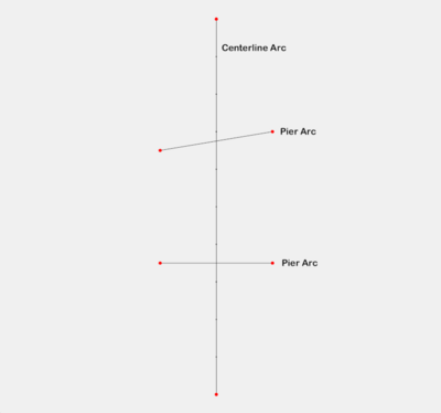
- Input coverage – This can be any coverage but it represents a single bridge. The coverage will have no polygons or feature points (points that are not part of any arcs). The longest arc is interpreted as the bridge centerline. All other arcs in the coverage should cross, but not intersect this arc (intersecting would result in splitting both arcs). All other arcs (which cross the bridge centerline) are assumed to define the location of a wall pier or pier group, unless the "Has abutments" toggle is selected. In this case, the arcs that intersect the centerline closest to the ends of the centerline arc define the orientation of the bridge abutments at the ends of the centerline. See the figure in the examples below.
- Bridge width – Enter the total width of the bridge from upstream face to downstream face. The units (foot/meter) correspond to the display projection of SMS.
- Bridge wrapping width – Enter the width of a rows of cells created just upstream and just downstream of the bridge footprint. These will be quadrilateral cells to cleanly represent the flow entering/leaving the bridge region. This width is usually specified to transition from smaller cells under the bridge to larger/longer cells in the channels upstream and downstream of the bridge.
- Specify number of segments (toggle) – This allows the user to define a number of segments in the wrapping layer. Normally this number comes from the number of elements representing the bridge cross section (spacing on the centerline arc and number of piers). If the number of elements in the bridge cross section is significantly different from the number of elements in the channel, this option can be used to provide a transition.
- Has abutments (toggle) – Setting this option instructs the tool to interpret the first and last crossing arcs as abutment orientations. If the toggle is not selected, the abutments are created perpendicular to the bridge centerline.
- Pier type – Specify that the piers in this bridge will be wall piers or pier groups (mixed types of piers in a single bridge are not currently supported).
- Wall width (option for wall piers) – Enter the width of the wall piers.
- Element wrapping width (option for wall piers) – Enter the desired width of the element adjacent to the pier. It is expected that this will normally be a small value to represent the boundary layer next to the pier. The tool will transition from this width to the spacing along the centerline.
- Wall pier length (option for wall piers) – Enter the length of the wall piers (in direction of flow). (The length of the arcs is not important.)
- Wall pier number of side elements (option for wall piers) – Enter the number of elements that should be created in the direction of flow alongside the wall pier.
- Pier end type - Square/Round/Sharp (option for wall piers) – Enter the resolution for the end of the pier. Square puts 1 element/cell on the end of the pier, sharp puts 2, round puts 3. Normally "Square" results are sufficient.
- Pier diameter (option for pier groups) – Enter the diameter of the piers. (All piers currently have the same diameter.)
- Element wrapping width (option for pier groups) – Enter the desired width of the element adjacent to the pier. It is expected that this will normally be a small value to represent the boundary layer next to the pier. The tool will transition from this width to the spacing along the centerline.
- Number of piers in group (option for pier groups) – Enter an integer number of piers in a group.
- Pier group spacing (option for pier groups – Enter the distance (centroid to centroid) between piers in a pier group.
Output parameters
- Output grid – Enter the name of the grid to be created (representing the area under the bridge).
- Output coverage – Enter the name of the coverage to be created (representing the bridge footprint). The intent of this coverage is to incorporate this polygon into the mesh generation coverage for the simulation domain and define transition from the channels and embankments into the bridge region.
Current Location in toolbox
2D Mesh/Bridge Footprint
Examples
Example 1 – Simple Bridge with a Single Pier
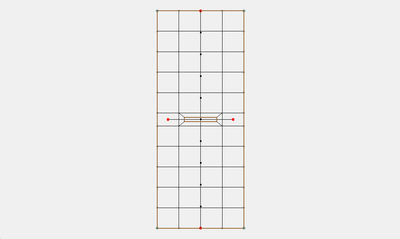
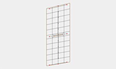
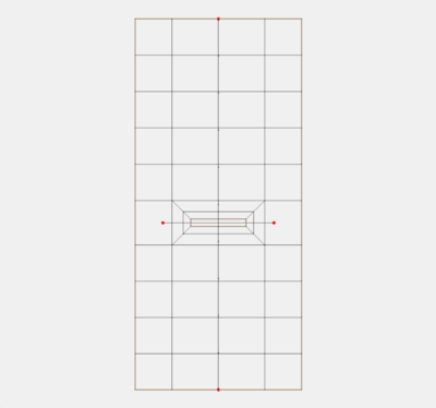
In this case the bridge width was set to 20.0, the wrapping width to 10.0. The pier is a wall pier with a width of 2, a wrapping width of 2 and a length of 15.0. Notice that the resulting elements above and below the pier do not line up with the vertices on the centerline arc. The vertices on the centerline arc are used to determine the number of segments between each pier and the segments are equally spaced between piers.
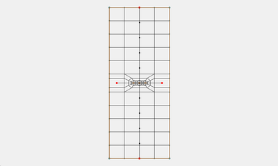
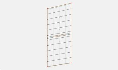
The next figure show a mesh where the pier type was changed to a pier group.
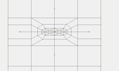
Zoomed in on the group
Example 2 – Bridge with Abutments and a Skewed Pier
In this case the bridge width was set to 20.0, the wrapping width to 10.0. The pier is a wall pier with a width of 2, a wrapping width of 2 and a length of 15.0. The “Has abutments” option was turned on. The skew of the pier and the abutments is parallel to the lines defining those features.
Example 3 – Box Culvert
This tool can also be used to insert a box culvert. Using the same coverage as the previous example, we will specify the pier length to be 20.0. This means the pier will intersect the bridge width. Whenever the length of the pier plus the wrapping width intersects the width of the bridge then the pier is treated like a wall in a box culvert. The next figure shows the resulting mesh.
Example 4 – Multiple Piers
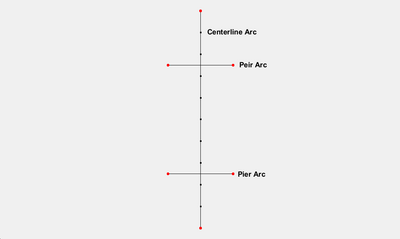
In this case the bridge width was set to 20.0, the wrapping width to 10.0. The pier is a wall pier with a width of 2, a wrapping width of 2 and a length of 15.0.
Example 5 – Multiple Piers 2
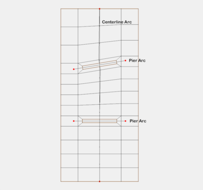
This is similar to the previous example except one of the piers is skewed.
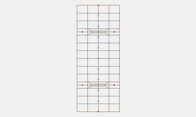
In this case the bridge width was set to 20.0, the wrapping width to 10.0. The pier is a wall pier with a width of 2, a wrapping width of 2 and a length of 15.0. Notice that because of the skew the number of elements is different on the upstream and downstream faces of the mesh. This forces transition elements (triangles) where the number of elements changes.
Example 6 – Intersecting Piers
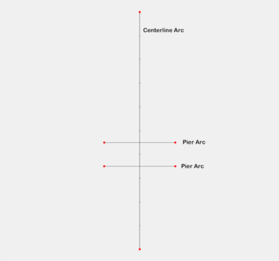
Sometimes piers may be close to one another as shown in the next example.
In this case the bridge width was set to 20.0, the wrapping width to 10.0. The pier is a wall pier with a width of 2, a wrapping width of 2 and a length of 10.0. With only the upper pier the mesh would look like the following figure.
When running the tool with both piers the tool will determine how large the piers can be without intersecting. Then another layer of elements will be placed between the piers and the bridge width.
The next figure shows the mesh with the bridge width reduced to 15.0 and wrapping width to 2.5 so that the final mesh has a width of 20.
