SMS:Total Flow Nodestring: Difference between revisions
No edit summary |
|||
| Line 3: | Line 3: | ||
The nodestring assigned as total flow will always be reported first in the table, and will always have 100% of the flowrate across it. The flux across all other cross sections will be reported in the continuity table as a percentage of this flowrate, whether it be more, less, or equal to 100%. Note that nodestrings should all be created from right to left, while looking downstream. When a nodestring is selected, arrows appear on its ends which show the assumed downstream direction. The figures below show advisable locations of the total flow nodestring. | The nodestring assigned as total flow will always be reported first in the table, and will always have 100% of the flowrate across it. The flux across all other cross sections will be reported in the continuity table as a percentage of this flowrate, whether it be more, less, or equal to 100%. Note that nodestrings should all be created from right to left, while looking downstream. When a nodestring is selected, arrows appear on its ends which show the assumed downstream direction. The figures below show advisable locations of the total flow nodestring. | ||
[[Image:TotalFlow1. | [[Image:TotalFlow1.png|400 px]] | ||
[[Image:TotalFlow2.gif]] | [[Image:TotalFlow2.gif]] | ||
Revision as of 16:12, 29 April 2016
Two hydrodynamic models supported by SMS, RMA2 and FST2DH, support a concept called the Total Flow Nodestring. These models print out a table of continuity or flux checks across specified nodestrings. Such checks are used to determine if there is mass loss through the model, to determine the amount of flow in various sections of a braided stream, or other similar purpose. In order to participate in the continuity table, the nodestring must either be assigned as a boundary condition or assigned as a flux (FST2DH) or geometric continuity (GC) (RMA2) string.
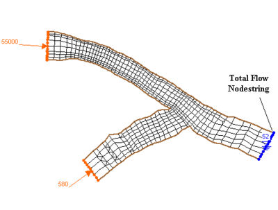
The nodestring assigned as total flow will always be reported first in the table, and will always have 100% of the flowrate across it. The flux across all other cross sections will be reported in the continuity table as a percentage of this flowrate, whether it be more, less, or equal to 100%. Note that nodestrings should all be created from right to left, while looking downstream. When a nodestring is selected, arrows appear on its ends which show the assumed downstream direction. The figures below show advisable locations of the total flow nodestring.
Related Topics
SMS – Surface-water Modeling System | ||
|---|---|---|
| Modules: | 1D Grid • Cartesian Grid • Curvilinear Grid • GIS • Map • Mesh • Particle • Quadtree • Raster • Scatter • UGrid |  |
| General Models: | 3D Structure • FVCOM • Generic • PTM | |
| Coastal Models: | ADCIRC • BOUSS-2D • CGWAVE • CMS-Flow • CMS-Wave • GenCade • STWAVE • WAM | |
| Riverine/Estuarine Models: | AdH • HEC-RAS • HYDRO AS-2D • RMA2 • RMA4 • SRH-2D • TUFLOW • TUFLOW FV | |
| Aquaveo • SMS Tutorials • SMS Workflows | ||
