GMS:Triangulation: Difference between revisions
No edit summary |
No edit summary |
||
| (11 intermediate revisions by one other user not shown) | |||
| Line 1: | Line 1: | ||
A TIN is constructed by triangulating a set of vertices. The vertices are connected with a series of edges to form a network of triangles. The resulting triangulation satisfies the | A TIN is constructed by triangulating a set of vertices. The vertices are connected with a series of edges to form a network of triangles. The resulting triangulation satisfies the Delaunay criterion. As the triangulation process proceeds, adjacent triangles are compared to see if they satisfy the Delaunay criterion. If necessary, the adjacent edge of the two triangles is swapped (the diagonal of the quadrilateral defined by the two triangles is changed to the other two vertices) in order to satisfy the Delaunay criterion. This edge swapping process forms the basis of the triangulation algorithm. | ||
When a new point is inserted into a TIN, the point is incorporated into the TIN and the edges of the triangles adjacent to the new point are swapped as necessary in order to satisfy the Delaunay criterion. | |||
The result | If the Delaunay criterion is satisfied everywhere on the TIN, the minimum interior angle of all of the triangles is maximized. The result is that long thin triangles are avoided as much as possible. The Delaunay criterion ensures that no vertex lies within the interior of any of the circumcircles of the triangles in the network as shown below: | ||
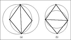
The vertices associated with the active TIN can be triangulated using the '''Triangulate''' command from the ''TIN'' menu, or by right-clicking on the TIN in the [[GMS:The GMS Window|Project Explorer]] and selecting the '''Triangulate''' command. | [[Image:DelaunayCriterion.jpg|thumb|center|250px|Two Adjacent Triangles Which (a) Violate and (b) Honor the Delaunay Criterion]] | ||
The vertices associated with the active TIN can be triangulated using the '''Triangulate''' command from the ''TIN'' menu, or by right-clicking on the TIN in the [[GMS:The GMS Window|Project Explorer]] and selecting the '''Triangulate''' command. The same '''Triangulate''' commands exist for 2D mesh in the ''Mesh'' menu or by right-clicking on the mesh. | |||
GMS also contains [[GMS:TIN Settings|settings]] for triangulation in the ''Preferences'' dialog for both TINs and meshes. | |||
| Line 18: | Line 22: | ||
{{Navbox GMS}} | {{Navbox GMS}} | ||
[[Category:TINs|T]] | |||
Latest revision as of 20:58, 24 April 2017
A TIN is constructed by triangulating a set of vertices. The vertices are connected with a series of edges to form a network of triangles. The resulting triangulation satisfies the Delaunay criterion. As the triangulation process proceeds, adjacent triangles are compared to see if they satisfy the Delaunay criterion. If necessary, the adjacent edge of the two triangles is swapped (the diagonal of the quadrilateral defined by the two triangles is changed to the other two vertices) in order to satisfy the Delaunay criterion. This edge swapping process forms the basis of the triangulation algorithm.
When a new point is inserted into a TIN, the point is incorporated into the TIN and the edges of the triangles adjacent to the new point are swapped as necessary in order to satisfy the Delaunay criterion.
If the Delaunay criterion is satisfied everywhere on the TIN, the minimum interior angle of all of the triangles is maximized. The result is that long thin triangles are avoided as much as possible. The Delaunay criterion ensures that no vertex lies within the interior of any of the circumcircles of the triangles in the network as shown below:
The vertices associated with the active TIN can be triangulated using the Triangulate command from the TIN menu, or by right-clicking on the TIN in the Project Explorer and selecting the Triangulate command. The same Triangulate commands exist for 2D mesh in the Mesh menu or by right-clicking on the mesh.
GMS also contains settings for triangulation in the Preferences dialog for both TINs and meshes.
See also
GMS – Groundwater Modeling System | ||
|---|---|---|
| Modules: | 2D Grid • 2D Mesh • 2D Scatter Point • 3D Grid • 3D Mesh • 3D Scatter Point • Boreholes • GIS • Map • Solid • TINs • UGrids | |
| Models: | FEFLOW • FEMWATER • HydroGeoSphere • MODAEM • MODFLOW • MODPATH • mod-PATH3DU • MT3DMS • MT3D-USGS • PEST • PHT3D • RT3D • SEAM3D • SEAWAT • SEEP2D • T-PROGS • ZONEBUDGET | |
| Aquaveo | ||
