GMS:2D Mesh Module: Difference between revisions
From XMS Wiki
Jump to navigationJump to search
No edit summary |
(→Mesh Element Types: typo) |
||
| (23 intermediate revisions by one other user not shown) | |||
| Line 1: | Line 1: | ||
{{2D Mesh links}} | {{2D Mesh links}} | ||
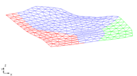
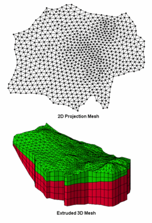
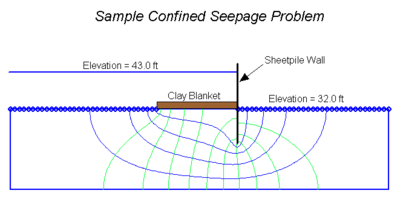
The 2D Mesh module is used to construct two-dimensional finite element meshes. Numerous tools are provided for automated mesh generation and mesh editing. 2D meshes are used for [[GMS:SEEP2D|SEEP2D]] modeling and to aid in the construction of 3D meshes. The figures below show an example of a SEEP2D model and a [[GMS:3D Mesh Module|3D mesh]] created using the 2D Mesh | The 2D Mesh module is used to construct two-dimensional finite element meshes. The mesh consists of nodes that are grouped together to form elements. Numerous [[GMS:2D Mesh Tool Palette|tools]] are provided for [[GMS:Creating a 2D Mesh|automated mesh generation]] and [[GMS:Editing 2D Meshes|mesh editing]]. 2D meshes are used for [[GMS:SEEP2D|SEEP2D]] modeling and to aid in the construction of 3D meshes. | ||
The figures below show an example of a SEEP2D model and a [[GMS:3D Mesh Module|3D mesh]] created using the 2D Mesh module. | |||
{| | {| | ||
|- | |- | ||
|[[Image:2d_to_3d_mesh. | |[[Image:2d_to_3d_mesh.png|thumb|none|300 px|3D Mesh created by extruding a 2D mesh]] | ||
| | |valign="top"|[[Image:samp_seep.png|thumb|none|400 px|Sample SEEP2D problem]] | ||
|[[Image:samp_seep. | |||
|} | |} | ||
The module contains its own [[GMS:2D Mesh Settings|settings]] and [[GMS:2D Mesh Display Options|display options]] including options to for contour and vector display. Currently, GMS only allows one 2D mesh to be included in a project. | |||
Datasets in a mesh store scalar or vector values at each node. Individual datasets can be duplicated or exported. | |||
2D mesh data can be exported from GMS by right-clicking on the 2D mesh and selecting the '''Export''' command. The entire mesh can be exported as a Text GMS 2D Mesh File (*.2dm), FEFLOW ASCII FEM Format (*.fem), Polygon Shapefile (*.shp), or Point Shapefile (*.shp). | |||
The 2D Mesh module can be added to a [http://www.aquaveo.com/software/gms-pricing paid edition] of GMS. | |||
[[Category:Link to Store]] | |||
==Mesh Element Types== | |||
Elements are used to describe the area to be modeled. Elements are formed by joining nodes. The element types supported vary from model to model. Element types include: | |||
* Three-node linear triangle | |||
* Six-node quadratic triangle | |||
* Eight-node "serendipity" quadrilateral | |||
* Nine-node "Lagrangian" quadrilateral | |||
{{Navbox GMS}} | {{Navbox GMS}} | ||
[[Category:2D Mesh]] | [[Category:2D Mesh]] | ||
[[Category:Mesh Modules]] | |||


