SMS:Patches: Difference between revisions
| Line 20: | Line 20: | ||
The elements in a new patch are checked to make sure they do not overlap each other. If any problems are detected, an error message is given and the patch is not created. Errors may occur especially when the region is highly irregular in shape. In such cases, the region can either be divided into smaller patches, or it can be filled using a different mesh generation technique. | The elements in a new patch are checked to make sure they do not overlap each other. If any problems are detected, an error message is given and the patch is not created. Errors may occur especially when the region is highly irregular in shape. In such cases, the region can either be divided into smaller patches, or it can be filled using a different mesh generation technique. | ||
=== | ===Rectangular Patch Hints=== | ||
The following are some hints when using rectangular patches: | The following are some hints when using rectangular patches: | ||
* The curvature of the patch can change somewhat, but it should not switch directions. If it does, then the patch should be split at the inflection point of the curve. | * The curvature of the patch can change somewhat, but it should not switch directions. If it does, then the patch should be split at the inflection point of the curve. | ||
Revision as of 23:10, 1 December 2017
Patching is a mesh generation technique used to fill the interior of a polygon. A polygon is assigned to be a patch in the Polygon Attributes dialog and is filled with the Map → 2D Mesh command.
The coordinates of the new nodes on the interior of the patch are computed by constructing a partial bicubic Coons patch using the polygon as patch edges. This ensures that interior nodes are smoothly interpolated from the nodes making up the perimeter of the patch. Patches are applicable when the data points are gathered along parallel lines, such as cross sections in a river.
It is recommended that a patch be applied before generating a mesh using the 2D Mesh Polygon Properties dialog.
Rectangular Patch
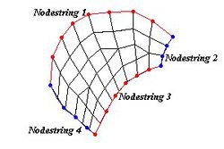
Elements can be made to fill a rectangular area by choosing the Rectangular Patch command from the Elements menu in the Mesh Module. To define a rectangular patch, four nodestrings must be selected. The nodestrings must connect at the ends.
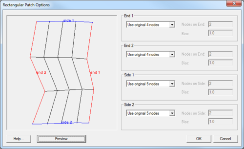
The coordinates of the new nodes on the interior of the patch are computed by constructing a partial bicubic Coons patch using the nodestrings as patch edges. This ensures that interior nodes are smoothly interpolated from the nodes making up the perimeter of the patch. Patches are applicable when the data points are gathered along parallel lines, such as cross sections in a river. The following options are available for each edge of the rectangular patch:
- Use original nodes – This option causes the original nodes from the nodestring to be used as corner nodes of elements along the boundary.
- Distribute nodes – This option distributes the specified number of nodes as corner nodes of elements along the boundary. If elements already exist on the boundary, then this option is unavailable.
- Bias – This is used with the Distribute nodes option. It causes the spacing of nodes along the nodestring to be weighted more to one of the corners.
After the spacing on each side is defined, click the Preview button to see how the patch will look. If changes are desired, they can be made. When the patch looks good, click the OK button to accept it. The patch can be canceled by clicking the Cancel button. Be careful to use the preview button because THERE IS NO UNDO FOR THIS OPERATION.
The elements in a new patch are checked to make sure they do not overlap each other. If any problems are detected, an error message is given and the patch is not created. Errors may occur especially when the region is highly irregular in shape. In such cases, the region can either be divided into smaller patches, or it can be filled using a different mesh generation technique.
Rectangular Patch Hints
The following are some hints when using rectangular patches:
- The curvature of the patch can change somewhat, but it should not switch directions. If it does, then the patch should be split at the inflection point of the curve.
- Although opposite sides in the rectangular patch are not required to have the same number of nodes, the best patches occur when this is close. In the example shown above, the two ends have the same number of nodes and the two sides only differ by three nodes.
Triangular Patch
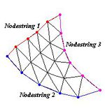
Elements can be made to fill a triangular area by choosing the Triangular Patch command from the Elements menu. To define a triangular patch, three nodestrings must be selected. The nodestrings must connect at the ends.
The coordinates of the new nodes on the interior of the patch are computed by constructing a partial bicubic Coons patch using the nodestrings as patch edges. This ensures that interior nodes are smoothly interpolated from the nodes making up the perimeter of the patch. The following options are available for each edge of the triangular patch:
- Use original nodes – This option causes the original nodes from the nodestring to be used as corner nodes of elements along the boundary.
- Distribute nodes – This option distributes the specified number of nodes as corner nodes of elements along the boundary. If elements already exist on the boundary, then this option is unavailable.
- Bias – This is used with the Distribute nodes option. It causes the spacing of nodes along the nodestring to be weighted more to one of the corners.
All three sides of a triangular patch must have the same number of nodes. After the spacing on each side is defined, click the Preview button to see how the patch will look. If changes are desired, they can be made. When the patch looks good, click the OK button to accept it. The patch can be canceled by clicking the CANCEL button.
Be careful to use the preview button because THERE IS NO UNDO FOR THIS OPERATION.
The elements in a new patch are checked to make sure they do not overlap each other. If any problems are detected, an error message is given and the patch is not created. Errors may occur especially when the region is highly irregular in shape. In such cases, the region can either be divided into smaller patches, or it can be filled using a different mesh generation technique.
Triangular Patch Hints
All three sides of a triangular patch must have the same number of nodes.
Errors
When the patch is previewed in the Polygon Attributes dialog, the elements in a new patch are checked to make sure they do not overlap each other. If any problems are detected, an error message is given and the patch is not created. Errors may occur especially when the region is highly irregular in shape. In such cases, the region can either be divided into smaller patches, or it can be filled using a different mesh generation technique.
If a polygon cannot be patched, a help string under the preview window in the Polygon Attributes dialog explains what needs to be changed.
Related Topics
SMS – Surface-water Modeling System | ||
|---|---|---|
| Modules: | 1D Grid • Cartesian Grid • Curvilinear Grid • GIS • Map • Mesh • Particle • Quadtree • Raster • Scatter • UGrid |  |
| General Models: | 3D Structure • FVCOM • Generic • PTM | |
| Coastal Models: | ADCIRC • BOUSS-2D • CGWAVE • CMS-Flow • CMS-Wave • GenCade • STWAVE • WAM | |
| Riverine/Estuarine Models: | AdH • HEC-RAS • HYDRO AS-2D • RMA2 • RMA4 • SRH-2D • TUFLOW • TUFLOW FV | |
| Aquaveo • SMS Tutorials • SMS Workflows | ||


