GMS:UGrid Linear Interpolation: Difference between revisions
No edit summary |
No edit summary |
||
| Line 1: | Line 1: | ||
__NOINDEX__ | __NOINDEX__ | ||
{{Version GMS 10.4}} | {{Version GMS 10.4}} | ||
[[File:Interpolate-Linear.png|thumb|350 px|The ''Interpolate – Linear'' dialog]] | |||
The Linear interpolation scheme uses data points that are first triangulated to form a network of triangles. The network of triangles only covers the convex hull of the point data, making extrapolation beyond the convex hull not possible. | The Linear interpolation scheme uses data points that are first triangulated to form a network of triangles. The network of triangles only covers the convex hull of the point data, making extrapolation beyond the convex hull not possible. | ||
| Line 28: | Line 29: | ||
:{{hide in print|[[File:convex_hull.jpg|thumb|none|left|300 px|Network of triangles]]}} | :{{hide in print|[[File:convex_hull.jpg|thumb|none|left|300 px|Network of triangles]]}} | ||
:{{only in print|[[File:convex_hull.jpg|275px|frame|center|Network of triangles]]}} | :{{only in print|[[File:convex_hull.jpg|275px|frame|center|Network of triangles]]}} | ||
If the Linear interpolation method is selected in the ''Interpolate UGrid to UGrid'' dialog, options can be set in the ''Interpolate – Linear'' dialog. This dialog has the following options: | If the Linear interpolation method is selected in the ''Interpolate UGrid to UGrid'' dialog, options can be set in the ''Interpolate – Linear'' dialog. This dialog has the following options: | ||
Revision as of 17:46, 31 August 2018
| This contains information about functionality available starting at GMS version 10.4. The content may not apply to other versions. |
The Linear interpolation scheme uses data points that are first triangulated to form a network of triangles. The network of triangles only covers the convex hull of the point data, making extrapolation beyond the convex hull not possible.
If the linear interpolation scheme is selected, the data points are first triangulated to form a network of triangles. The equation of the plane defined by the three vertices of a triangle is as follows:
- where A, B, C, and D are computed from the coordinates of the three vertices (x1,y1,z1), (x2,y2,z2), and (x3,y3,z3):
The plane equation can also be written as:
- which is the form of the plane equation used to compute the elevation at any point on the triangle.
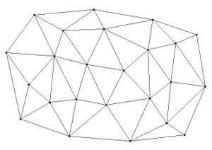
Since the network of triangles only covers the convex hull of the point data, extrapolation beyond the convex hull is not possible with the linear interpolation scheme. Any points outside the convex hull of the point data are assigned the default extrapolation value entered at the bottom of the Interpolation Options dialog. The figure below shows a network of triangles created from point data.
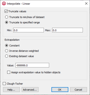
If the Linear interpolation method is selected in the Interpolate UGrid to UGrid dialog, options can be set in the Interpolate – Linear dialog. This dialog has the following options:
- Truncate values – This section allows for limiting the interpolated values to lie between the minimum and maximum value.
- Truncate to min/max of dataset – Limits the interpolated values to the minimum and maximum values in the original dataset.
- Truncate to specified range – Allows setting a user specified minimum and maximum value range.
- Min – Manually sets a minimum value.
- Max – Manually sets a maximum value.
- Clough-Tocher – When on, the Clough-Tocher interpolation technique will be used.
- Advanced – This button will open the Interpolate – Advanced dialog where options for anisotropy and extrapolation can be adjusted.
Related Topics
GMS – Groundwater Modeling System | ||
|---|---|---|
| Modules: | 2D Grid • 2D Mesh • 2D Scatter Point • 3D Grid • 3D Mesh • 3D Scatter Point • Boreholes • GIS • Map • Solid • TINs • UGrids | |
| Models: | FEFLOW • FEMWATER • HydroGeoSphere • MODAEM • MODFLOW • MODPATH • mod-PATH3DU • MT3DMS • MT3D-USGS • PEST • PHT3D • RT3D • SEAM3D • SEAWAT • SEEP2D • T-PROGS • ZONEBUDGET | |
| Aquaveo | ||


