User:Jcreer/SMS:3D Bridge: Difference between revisions
From XMS Wiki
Jump to navigationJump to search
| Line 44: | Line 44: | ||
**''Elevation'' – Elevation of the given distance. | **''Elevation'' – Elevation of the given distance. | ||
*Preview area – Displays a preview of the profile. | *Preview area – Displays a preview of the profile. | ||
{{Navbox SMS}} | {{Navbox SMS}} | ||
[[Category:SMS General Information]] | [[Category:SMS General Information]] | ||
Revision as of 20:55, 21 August 2019
| This contains information about functionality available starting at SMS version 13.1. The content may not apply to other versions. |
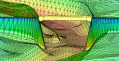
A 3D bridge can be modeled on an existing model using components. To model a 3D bridge, the following is needed:
- Area Property coverage
- Two arcs on the Area Property coverage defining the upstream and downstream sides of the bridge
- Top, upstream, and downstream profiles
Also, having an existing mesh, scatter set, or grid of the site is typically helpful.
To build a 3D bridge, do the following:
- Create an Area Property coverage.
- Create arcs representing the upstream and downstream side of the bridge location.
- Right-click in the Project Explorer and select New General Component | Bridge.
- Link the Area Property Coverage to the component in the Project Explorer.
- Right-click on the component item and select Edit Bridge.
- In the Bridge dialog, define the top profile, upstream profile, and downstream profile.
- Export the 3D bridge and save out the XMUGRID file.
- Import the XMUGRID file.
3D Bridge Modeling Tips
- The first arc drawn on the Area Properties coverage will be made the upstream arc by default. Use the Swap Arcs button in the Bridge dialog to change this.
- The bridge will use the same units as set in the project's projection.
- Multiple bridges can be modeled by creating addition components.
- When exporting the bridge, the XMUGRID file is created as well as a PRJ file containing the bridge's projection. These files should be kept together.
Components
Bridge Dialog
The Bridge dialog is reached by right-clicking on a bridge component and selecting the Edit Bridge command. The dialog contains the following options:
- Swap Arcs – Changes which arc is the upstream arc and which is the downstream arc.
- Export 3D Bridge – Brings up a Save dialog where the bridge can be saved as a ugrid.
- Top Profile –
- Edit – Launches the XY Series Editor for the bridge profiles.
- Upstream Profile
- Edit – Launches the XY Series Editor for the bridge profiles.
- Downstream Profile
- Edit – Launches the XY Series Editor for the bridge profiles.
XY Series Editor
This dialog is reached through the Bridge dialog. The dialog contains the following:
- Number of Rows – Defines the number of rows available in the spreadsheet.
- Spreadsheet – Contains values for the profile distance and elevation.
- Distance – Location along the arc. The distance starts at the first node in the arc and moves in the same direction as the arc.
- Elevation – Elevation of the given distance.
- Preview area – Displays a preview of the profile.
SMS – Surface-water Modeling System | ||
|---|---|---|
| Modules: | 1D Grid • Cartesian Grid • Curvilinear Grid • GIS • Map • Mesh • Particle • Quadtree • Raster • Scatter • UGrid |  |
| General Models: | 3D Structure • FVCOM • Generic • PTM | |
| Coastal Models: | ADCIRC • BOUSS-2D • CGWAVE • CMS-Flow • CMS-Wave • GenCade • STWAVE • WAM | |
| Riverine/Estuarine Models: | AdH • HEC-RAS • HYDRO AS-2D • RMA2 • RMA4 • SRH-2D • TUFLOW • TUFLOW FV | |
| Aquaveo • SMS Tutorials • SMS Workflows | ||
