GMS:SEEP2D: Difference between revisions
From XMS Wiki
Jump to navigationJump to search
| (39 intermediate revisions by 2 users not shown) | |||
| Line 1: | Line 1: | ||
{{Infobox Model | | {{Infobox Model | | ||
|name= SEEP2D | |name= SEEP2D | ||
|screenshot= Image:samp_seep. | |screenshot= Image:samp_seep.png | ||
|model_type= 2D seepage, confined or unconfined, steady state | |model_type= 2D seepage, confined or unconfined, steady state | ||
|developer= Fred Tracy, [http://www.erdc.usace.army.mil/ ERDC] | |developer= Fred Tracy, [http://www.erdc.usace.army.mil/ ERDC] | ||
| Line 14: | Line 14: | ||
Portions of a SEEP2D model can be imported from [[GMS:GeoStudio Import|GeoStudio]] files. | Portions of a SEEP2D model can be imported from [[GMS:GeoStudio Import|GeoStudio]] files. | ||
The SEEP2D model can be added to a [http://www.aquaveo.com/software/gms-pricing paid edition] of GMS. | |||
[[Category:Link to Store]] | |||
==Building a SEEP2D Simulation== | ==Building a SEEP2D Simulation== | ||
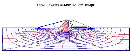
[[Image:flownet1. | [[Image:flownet1.png|thumb|right|500 px|Sample flow net from SEEP2D]] | ||
For a typical application, the following steps are used to perform a SEEP2D simulation using GMS: | Creating a SEEP2D model in GMS requires using the [[GMS:Preferences#Program_Mode|GMS 2D program mode]]. For a typical application, the following steps are used to perform a SEEP2D simulation using GMS: | ||
#'''Generate a 2D mesh''' – The first step in setting up a SEEP2D simulation is to construct a 2D finite element mesh. This can be accomplished using the ''Feature Objects'' | '''Map → 2D Mesh''' command in the [[GMS:Map Module|Map module]]. SEEP2D only supports meshes composed entirely of linear elements (three node triangles and four node quadrilaterals). The mesh should not contain quadratic elements (six node triangles and eight node quadrilaterals). | #'''Generate a 2D mesh''' – The first step in setting up a SEEP2D simulation is to construct a 2D finite element mesh. This can be accomplished using the ''Feature Objects'' | '''Map → 2D Mesh''' command in the [[GMS:Map Module|Map module]]. SEEP2D only supports meshes composed entirely of linear elements (three node triangles and four node quadrilaterals). The mesh should not contain quadratic elements (six node triangles and eight node quadrilaterals). | ||
#'''Select the analysis options''' – The analysis options are used to set up the type of problem being modeled and to defined constants that are used by SEEP2D when calculating the solution | #'''Select the analysis options''' – The analysis options are used to set up the type of problem being modeled and to defined constants that are used by SEEP2D when calculating the solution. This is done in the ''SEEP2D Analysis Options'' dialog. ([[GMS:SEEP2D#SEEP2D Analysis Options|See below.]]) | ||
#'''Assign the material properties''' – Each element in the 2D mesh is assigned a material ID. The material properties are assigned to each element using these IDs and a list of material properties. | |||
#'''Assign the boundary conditions''' (either with a conceptual model or with the 2D mesh tools) – Two general types of boundary conditions can be defined for SEEP2D simulations: nodal boundary conditions and flux boundary conditions. (See [[GMS:SEEP2D#SEEP2D Boundary Conditions|SEEP2D Boundary Conditions]]) | |||
# | |||
#'''Assign the material properties''' – Each element in the 2D mesh is assigned a material ID. The material properties are assigned to each element using these IDs and a list of material properties | |||
#'''Assign the boundary conditions''' (either with a conceptual model or with the 2D mesh tools) | |||
#'''Run the [[GMS:Model Checker|Model Checker]].''' | #'''Run the [[GMS:Model Checker|Model Checker]].''' | ||
#'''Save the simulation''' | #'''Save the simulation''' | ||
#'''Run the simulation''' | #'''Run the simulation''' | ||
#'''Display the results''' – Before reading in the solution file for post-processing in GMS, it is often useful to examine the text output listing file. The output file can also be viewed by simply double-clicking on the *.out file found in the [[GMS:SEEP2D Solution|SEEP2D solution]] folder in the [[GMS:The GMS | #'''Display the results''' – Before reading in the solution file for post-processing in GMS, it is often useful to examine the text output listing file. The output file can also be viewed by simply double-clicking on the *.out file found in the [[GMS:SEEP2D Solution|SEEP2D solution]] folder in the [[GMS:The GMS Window|Project Explorer]]. Also, any text file can be viewed by selecting the '''Edit File''' command in the ''File'' menu. The File Browser appears and the selected file is opened in a text editor. Once the solution is imported to GMS, a variety of options are available for displaying the solution. The total head and pressure head datasets can be contoured. Velocity vectors corresponding to Darcy velocity can be plotted. If the ''Compute flow lines'' option was selected, a complete flow net may be plotted by displaying contours of total head (equipotential lines) and turning on the ''Flow lines'' option in the ''SEEP2D Display Options'' dialog. | ||
==SEEP2D Boundary Conditions== | ==SEEP2D Boundary Conditions== | ||
Two general types of boundary conditions can be defined for SEEP2D simulations: nodal boundary conditions and flux boundary conditions. The type or value assigned to a previously defined boundary condition can be edited by selecting the node or node string and selecting either the | Two general types of boundary conditions can be defined for SEEP2D simulations: nodal boundary conditions and flux boundary conditions. The type or value assigned to a previously defined boundary condition can be edited by selecting the node or node string and selecting either the '''Node BC''' or '''Flux BC''' commands. A boundary condition can be deleted by selecting the boundary condition using either the '''Select Node''' or '''Select Node String''' tools and selecting the '''Delete BC''' command in the ''SEEP2D'' menu. | ||
===Nodal Boundary Conditions=== | ===Nodal Boundary Conditions=== | ||
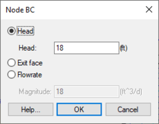
The most common type of SEEP2D boundary conditions is nodal boundary conditions. Nodal boundary conditions are assigned by selecting the nodes and selecting the | The most common type of SEEP2D boundary conditions is nodal boundary conditions. Nodal boundary conditions are assigned by selecting the nodes and selecting the '''Node BC''' command in the ''SEEP2D'' menu. When selecting the nodes, either the [[GMS:2D Mesh Tool Palette|'''Select Node''']] tool or the [[GMS:2D Mesh Tool Palette|'''Select Node String''']] tool may be used. The '''Node BC''' command brings up the ''Node BC'' dialog. Three types of nodal boundary conditions can be assigned: head, exit face, and flow rate. | ||
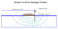
[[Image:SEEP2D_CM. | [[Image:SEEP2D_CM.png|thumb|right|500 px|Sample SEEP2D problem showing boundary conditions]] | ||
*'''Head BC''' – Specified head boundary conditions represent boundaries where the head is known. They typically are found where water is ponding or at the boundary of a region where the water table is known to remain constant. Since the head along such boundaries cannot change, they represent regions of the model where flow enters or exits the system (flow lines are always orthogonal to constant head boundaries). | *'''Head BC''' – Specified head boundary conditions represent boundaries where the head is known. They typically are found where water is ponding or at the boundary of a region where the water table is known to remain constant. Since the head along such boundaries cannot change, they represent regions of the model where flow enters or exits the system (flow lines are always orthogonal to constant head boundaries). | ||
*'''Exit Face BC''' – Exit face boundary conditions | *'''Exit Face BC''' – Exit face boundary conditions are used when modeling unconfined flow problems and should be placed along the face where the free surface is likely to exit the model. If the head at a node with an exit face bc becomes greater than the node elevation during the iteration process, the head at the node is fixed at the nodal elevation and the node acts as a specified head boundary. Thus, water is allowed to exit the model at that node. | ||
*'''Flow Rate BC''' – Flow rate boundary conditions are used to specify nodes at which a certain flow rate is known to exist. They are used primarily when modeling wells and the flow specified represents the pumping rate. Negative values represent extraction of fluid from the system whereas positive values represent injection. | *'''Flow Rate BC''' – Flow rate boundary conditions are used to specify nodes at which a certain flow rate is known to exist. They are used primarily when modeling wells and the flow specified represents the pumping rate. Negative values represent extraction of fluid from the system whereas positive values represent injection. | ||
[[File:SEEP2DnodeBC.png|thumb|none|left|230 px|The SEEP2D ''Node BC'' dialog.]] | |||
===Flux Boundary Conditions=== | ===Flux Boundary Conditions=== | ||
Flux boundary conditions are used to specify a known flux rate [L/T] along a sequence of element edges on the perimeter of the mesh. They are often used to simulate infiltration. Flux into the system is positive and flux out of the system is negative. | Flux boundary conditions are used to specify a known flux rate [L/T] along a sequence of element edges on the perimeter of the mesh. They are often used to simulate infiltration. Flux into the system is positive and flux out of the system is negative. | ||
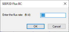
Flux BC are assigned by selecting a sequence of nodes along the mesh boundary using the Select Node String tool and selecting the | Flux BC are assigned by selecting a sequence of nodes along the mesh boundary using the '''Select Node String''' tool and selecting the '''Flux BC''' command in the ''SEEP2D'' menu. This command brings up a simple prompt for the flow rate. | ||
[[File:SEEP2DfluxBC.png|thumb|none|left|240 px|The ''SEEP2D Flux BC'' dialog.]] | |||
==SEEP2D Materials== | |||
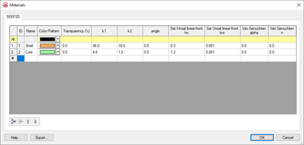
The material properties specific to SEEP2D are entered using the '''Material''' command in the ''Edit'' menu. This command brings up the ''SEEP2D'' tab of the ''Materials'' dialog. | |||
The options in the dialog are as follows: | |||
*''List of Materials'' – The currently defined materials are listed at the top of the dialog. The values for a material are entered by selecting the material and editing the values in the lower part of the dialog. | |||
*''Soil Coefficients'' – The hydraulic conductivity in the two major principal directions and the angle from the x-axis to the major principal axis are entered in the Soil Coefficients section. These hydraulic conductivity values represent the hydraulic conductivity for saturated conditions. | |||
*''Van Genuchten Parameters'' – If the ''Van Genuchten Saturated/Unsaturated'' option has been selected in the ''SEEP2D Analysis Options'' dialog, the Van Genuchten alpha and n-value numbers must be defined. | |||
*''Linear Front Parameters'' – If the Saturated/Unsaturated with ''Linear Front'' option has been selected in the ''SEEP2D Analysis Options'' dialog, the minimum pressure head (ho) and minimum relative conductivity (kro) values must be defined. | |||
[[File:SEEP2D Materials.png|thumb|none|600 px|The ''SEEP2D'' tab of the ''Materials'' dialog]] | |||
==SEEP2D Analysis Options== | ==SEEP2D Analysis Options== | ||
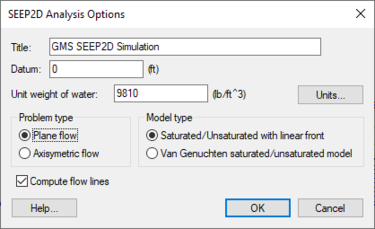
Options for the SEEP2D model can be set in the ''SEEP2D Analysis Options'' dialog. This dialog is accessed through the SEEP2D menu. | [[File:SEEP2Danalysis.png|thumb|375 px|''SEEP2D Analysis Options'' dialog]] | ||
[[ | Options for the SEEP2D model can be set in the ''SEEP2D Analysis Options'' dialog. This dialog is accessed through the ''SEEP2D'' menu. | ||
The items in the dialog are as follows: | |||
*''Title'' – A descriptive title can be entered for the simulation. This title is used in the header of the SEEP2D input and output files. It can also be displayed at the top of the Graphics Window in GMS by turning on the ''Title'' option in the [[GMS:SEEP2D Display Options|''SEEP2D Display'' Options]] dialog. | |||
*''Datum'' – By default, the datum of the model is at zero, but it can be specified to any convenient value, such as the value corresponding to the base or lowest y coordinate of the model. | |||
*''Unit Weight of Water'' – The unit weight of water must be entered. SEEP2D uses this value to compute pore pressures. The weight and length units defined in this value should be consistent with the units used elsewhere in the model. | |||
*''Units'' – The '''Units''' button brings up the [[GMS:Units|''Units'']] dialog. This dialog is used to enter the units for length, time, concentration, etc. for the simulation. GMS uses the selected unit options to display the appropriate units next to each input edit field in the other SEEP2D dialogs. | |||
*''Problem Type'' – The problem type must be specified either as plane flow or axisymmetric flow. The ''Axisymmetric'' option should be selected for models corresponding to flow to a single well as described in the SEEP2D Primer. All other models should use the ''Plane flow'' option. | |||
*''Flow Lines'' – If the ''Compute flow lines'' option is turned on, once the head solution is computed, SEEP2D will reverse the boundary conditions and compute flow potential values at the nodes. These values can be contoured by GMS using the ''Flow lines'' option is the ''SEEP2D Display Options'' dialog. | |||
*''Model Type'' – The hydraulic conductivity in the unsaturated zone is modified (reduced) using either the linear frontal method or the Van Genuchten method. The equations used by both methods are described in more detail in the SEEP2D Primer. | |||
==Reading the [[GMS:SEEP2D Solution|SEEP2D Solution]]== | ==Reading the [[GMS:SEEP2D Solution|SEEP2D Solution]]== | ||
The solution can be imported into GMS using the '''Read Solution''' command in the ''SEEP2D'' menu. Also at the end of a SEEP2D run the solution is automatically imported to GMS. The solution files are organized in a SEEP2D solution folder in the [[GMS:The GMS Window|Project Explorer]]. | |||
==SEEP2D Files== | ==SEEP2D Files== | ||
| Line 69: | Line 84: | ||
[[Category:SEEP2D]] | [[Category:SEEP2D]] | ||
[[Category:2D Mesh]] | [[Category:2D Mesh]] | ||
[[Category:SEEP2D Dialogs]] | |||
[[Category:External Links]] | |||
