SMS:RMA2 1D Control Structures: Difference between revisions
| (4 intermediate revisions by the same user not shown) | |||
| Line 1: | Line 1: | ||
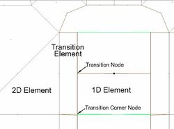
[[Image:RMA2_Transition_Element.jpg|thumb|right|250px|Example RMA2 transition element from 2D mesh to 1D element.]] | |||
[[Image:RMA2_Transition_Element.jpg|thumb|right| | |||
In [[SMS:RMA2|RMA2]], a one-dimensional Control Structure element is a single point which contains two nodes and has an IMAT value ≥ 904. The order of the node numbering at a Control Structure element should be that the side with higher elevation comes first, then the side with the lower elevation. This is generally the “upstream” side of the structure followed by the “downstream” side. This order sets the “orientation” of the flow through the structure. | In [[SMS:RMA2|RMA2]], a one-dimensional Control Structure element is a single point which contains two nodes and has an IMAT value ≥ 904. The order of the node numbering at a Control Structure element should be that the side with higher elevation comes first, then the side with the lower elevation. This is generally the “upstream” side of the structure followed by the “downstream” side. This order sets the “orientation” of the flow through the structure. | ||
| Line 22: | Line 21: | ||
Weirs also give hydrologists and engineers a simple method of measuring the rate of fluid flow in small to medium sized streams. Since the geometry of the top of the weir is known, and all water flows over the weir, the depth of water flowing over the weir will be an indication of the flow. There are different types of weir. It may be a simple metal plate with a V notch cut into it or it may be a concrete and steel structure across the bed of a river. A v-notch weir will give a more accurate indication of low flow rates. | Weirs also give hydrologists and engineers a simple method of measuring the rate of fluid flow in small to medium sized streams. Since the geometry of the top of the weir is known, and all water flows over the weir, the depth of water flowing over the weir will be an indication of the flow. There are different types of weir. It may be a simple metal plate with a V notch cut into it or it may be a concrete and steel structure across the bed of a river. A v-notch weir will give a more accurate indication of low flow rates. | ||
==1D Node Geometry Dialog== | |||
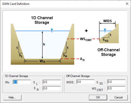
[[File:Assign 1D Geometry.png|thumb|none|450 px|The ''GWN Card Definition'' dialog used for 1D node geometry]] | |||
{{Stub}} | |||
== Related Topics == | == Related Topics == | ||
Latest revision as of 16:37, 11 May 2020
In RMA2, a one-dimensional Control Structure element is a single point which contains two nodes and has an IMAT value ≥ 904. The order of the node numbering at a Control Structure element should be that the side with higher elevation comes first, then the side with the lower elevation. This is generally the “upstream” side of the structure followed by the “downstream” side. This order sets the “orientation” of the flow through the structure.
Since flow through and over some structures does not fit the 2D assumptions, some structures can be represented as 1D components in the 2D mesh. These include weirs, culverts, drop inlets and some gates.
There are strict rules that must be followed in order to get convergence with 1D elements in RMA2. These rules include:
- Transition elements must be connected to the free end of a 2D element. The element should not be connected to other 2D elements on the sides.
- The transition element must be perpendicular to the free end of the 2D element.
- The bottom elevation of the free end should be flat.
- Control structure elements cannot be constructed on transition elements.
Culvert
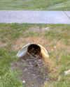
A culvert is a conduit used to enclose a flowing body of water. It may be used to allow water to pass underneath a road, railway, or embankment, for example. Culverts can be made of many different materials; steel, polyvinyl chloride (PVC) and concrete are the most common.
Culvert flow rate depends primarily on headwater depth. Other factors that affect flow rate are tailwater elevation and properties of the culvert such as shape, cross sectional area, inlet geometry, length, slope, and roughness.
Weir
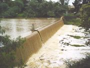
A weir is a small overflow-type dam commonly used to raise the level of a river or stream. Weirs have traditionally been used to create mill ponds in such places. Water flows over the top of a weir, although some weirs have sluice gates which release water at a level below the top of the weir. The crest of an overflow spillway on a large dam is often called a weir.
Weirs also give hydrologists and engineers a simple method of measuring the rate of fluid flow in small to medium sized streams. Since the geometry of the top of the weir is known, and all water flows over the weir, the depth of water flowing over the weir will be an indication of the flow. There are different types of weir. It may be a simple metal plate with a V notch cut into it or it may be a concrete and steel structure across the bed of a river. A v-notch weir will give a more accurate indication of low flow rates.
1D Node Geometry Dialog
Related Topics
SMS – Surface-water Modeling System | ||
|---|---|---|
| Modules: | 1D Grid • Cartesian Grid • Curvilinear Grid • GIS • Map • Mesh • Particle • Quadtree • Raster • Scatter • UGrid |  |
| General Models: | 3D Structure • FVCOM • Generic • PTM | |
| Coastal Models: | ADCIRC • BOUSS-2D • CGWAVE • CMS-Flow • CMS-Wave • GenCade • STWAVE • WAM | |
| Riverine/Estuarine Models: | AdH • HEC-RAS • HYDRO AS-2D • RMA2 • RMA4 • SRH-2D • TUFLOW • TUFLOW FV | |
| Aquaveo • SMS Tutorials • SMS Workflows | ||


