GMS:Bounding Grid: Difference between revisions
No edit summary |
No edit summary |
||
| (9 intermediate revisions by 3 users not shown) | |||
| Line 1: | Line 1: | ||
{{3D Scatter Point links}} | {{3D Scatter Point links}} | ||
In many cases, it is useful to interpolate to a 3D grid which just contains the 3D scatter | In many cases, it is useful to interpolate to a 3D grid which just contains the points from a 3D scatter set. The '''Bounding Grid''' command was designed in order to simplify the creation of such a grid. Selecting the '''Bounding Grid''' command from the ''Scatter Points'' menu brings up the ''Create Finite Difference Grid'' dialog pre-filled with grid dimensions set at 10% beyond the bounds of the active scatter point set. | ||
''Origin, Length, Rotation'' – By default, the rows and columns of 2D grids are aligned with the x and y axes. However, grids can be rotated about the z-axis, if desired. Thus, the information needed to determine the overall size and location of the grid is the xy coordinates of the lower left corner of the grid (the lower left corner prior to rotation), the length of the grid in the x and y directions, and the rotation angle. The xy coordinates of the origin are entered in the ''Origin'' edit fields, the dimensions are entered in the ''Length'' fields, and the angle of rotation is entered in the field entitled ''Rotation'' about Z-axis. | |||
''Bias'' – Several options are available for defining the number and locations of the cell boundaries. A bias can be defined which controls how the cell size varies from one cell to the next. For example, an X bias of 1.5 causes each cell to be 50% larger than the previous cell when moving in the positive x direction. | |||
''Number of Cells'' – The total number of cells in each direction (number of rows or columns) can be defined by explicitly entering a number or by entering a base cell size and a limit cell size. The base and limit cell size options are used when a bias other than 1.0 is specified. The base cell size is the size of the first cell in the sequence. The cells are then generated by altering the cell size according to the bias until the limit cell size is reached. The remainder of the cells are constructed using the limit cell size. | |||
''Type and Orientation'' – The controls at the bottom of the ''Create Grid'' dialog are used to define the type and orientation of the grid. Specify whether the grid should be a mesh-centered grid or a cell-centered grid. The orientation of the ij axes with respect to the XY axes can also be specified. | |||
See [[GMS:2D_Grid_Creation_and_Editing#Create_Grid|Create Grid]] for more information on this dialog. | |||
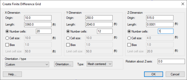
[[File:CreateFiniteDifferenceGrid.png|thumb|none|600 px|The ''Create Finite Difference Grid'' dialog]] | |||
{{Navbox GMS}} | {{Navbox GMS}} | ||
[[Category:3D Scatter Point]] | [[Category:3D Scatter Point]] | ||
[[Category:GMS Dialogs]] | |||
Latest revision as of 15:41, 18 July 2016
In many cases, it is useful to interpolate to a 3D grid which just contains the points from a 3D scatter set. The Bounding Grid command was designed in order to simplify the creation of such a grid. Selecting the Bounding Grid command from the Scatter Points menu brings up the Create Finite Difference Grid dialog pre-filled with grid dimensions set at 10% beyond the bounds of the active scatter point set.
Origin, Length, Rotation – By default, the rows and columns of 2D grids are aligned with the x and y axes. However, grids can be rotated about the z-axis, if desired. Thus, the information needed to determine the overall size and location of the grid is the xy coordinates of the lower left corner of the grid (the lower left corner prior to rotation), the length of the grid in the x and y directions, and the rotation angle. The xy coordinates of the origin are entered in the Origin edit fields, the dimensions are entered in the Length fields, and the angle of rotation is entered in the field entitled Rotation about Z-axis.
Bias – Several options are available for defining the number and locations of the cell boundaries. A bias can be defined which controls how the cell size varies from one cell to the next. For example, an X bias of 1.5 causes each cell to be 50% larger than the previous cell when moving in the positive x direction.
Number of Cells – The total number of cells in each direction (number of rows or columns) can be defined by explicitly entering a number or by entering a base cell size and a limit cell size. The base and limit cell size options are used when a bias other than 1.0 is specified. The base cell size is the size of the first cell in the sequence. The cells are then generated by altering the cell size according to the bias until the limit cell size is reached. The remainder of the cells are constructed using the limit cell size.
Type and Orientation – The controls at the bottom of the Create Grid dialog are used to define the type and orientation of the grid. Specify whether the grid should be a mesh-centered grid or a cell-centered grid. The orientation of the ij axes with respect to the XY axes can also be specified.
See Create Grid for more information on this dialog.
GMS – Groundwater Modeling System | ||
|---|---|---|
| Modules: | 2D Grid • 2D Mesh • 2D Scatter Point • 3D Grid • 3D Mesh • 3D Scatter Point • Boreholes • GIS • Map • Solid • TINs • UGrids | |
| Models: | FEFLOW • FEMWATER • HydroGeoSphere • MODAEM • MODFLOW • MODPATH • mod-PATH3DU • MT3DMS • MT3D-USGS • PEST • PHT3D • RT3D • SEAM3D • SEAWAT • SEEP2D • T-PROGS • ZONEBUDGET | |
| Aquaveo | ||

