GMS:HydroGeoSphere: Difference between revisions
From XMS Wiki
Jump to navigationJump to search
No edit summary |
|||
| (55 intermediate revisions by 2 users not shown) | |||
| Line 1: | Line 1: | ||
{{ | {{HGS Links}} | ||
HydroGeoSphere (HGS) is a three-dimensional control-volume finite element simulator created by [https://www.aquanty.com/ Aquanty]. HGS can be used to model the entire terrestrial portion of the hydrologic cycle. It uses a globally-implicit approach to simultaneously solve the 2D diffusive-wave equation for overland/surface water flow and the 3D form of Richards’ equation for variably saturated groundwater flow. GMS allows multiple HGS simulations to exist in a single GMS project. Users should note that while GMS uses the terms “points” and “cells” for UGrids, HGS uses the terms “nodes” and “elements” regarding this tool. | |||
==HydroGeoSphere Simulations== | |||
The GMS interface for HydroGeoSphere contains multiple components. These components include: | |||
* An unstructured grid (UGrid) | |||
* [[GMS:HydroGeoSphere Coverages|HydroGeoSphere coverages]] | |||
* HydroGeoSphere simulation, including the [[GMS:HydroGeoSphere Simulation Control|Simulation Control]] | |||
*[[GMS: | ===Creating a New HydroGeoSphere Simulation === | ||
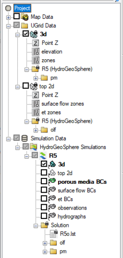
[[File:Hgs simulation.png|thumb|250 px|Example of a HydroGeoSphere simulation in the Project Explorer]] | |||
To create a HydroGeoSphere simulation: | |||
# Right-click on an empty space in the Project Explorer, or right-click on "[[File:Project Icon.svg|16 px]] Project" in the Project Explorer, and select ''New Simulation'' | '''HydroGeoSphere'''. | |||
A 3D UGrid of the project area is required. While the project can contain multiple UGrids, only one UGrid can be attached to each HGS simulation. The desired UGrid will need to be linked to the HGS simulation. | |||
===HGS Simulation Right-Click Menus=== | |||
In the Project Explorer, right-clicking on a HGS simulation brings up a menu with several commands. Some of these commands are common to other Project Explorer In the Project Explorer, right-clicking on HGS simulation brings up a menu with several commands. Some of these commands are common to other Project Explorer right-click menus. Others are unique to the simulation right-click menus. Some of these unique commands are: | |||
*"[[File:Mf6sim data.svg|16 px]] Simulation Data" | |||
**'''Simulation Run Queue''' – Opens the ''Simulation Run Queue'' dialog which shows all current simulation runs. | |||
*"[[File:Hgs-sim-folder icon.png|16 px]] HydroGeoSphere Simulations" | |||
** '''New Simulation''' – Creates a new HGS simulation in the Project Explorer. This simulation will not contain any of the packages in any existing simulations and therefor the packages must be added. Also, creating a new simulation using this method requires linking a UGrid to the simulation. | |||
** '''Save Multiple Simulations''' – Saves all HGS simulations in the project and exports all files needed for the model run. | |||
*[[File:HydroGeoSphere Simulation Icon.png|16 px]] Model | |||
**'''Simulation Control''' – Opens the [[GMS:HydroGeoSphere Simulation Control|''Simulation Control'']] dialog where the HGS simulation parameters are set. | |||
**'''Materials''' – Opens the HGS [[GMS:HydroGeoSphere Materials|''Materials'']] dialog. | |||
**'''Export''' – Saves out the simulation files. | |||
**'''Run grok''' – Opens the ''Run grok.exe'' dialog where GMS will generate the GROK file. The GROK file contains all of the information and instructions required for the HGS simulation. | |||
**'''Run phgs''' – Opens the ''Run phgs.exe'' dialog where the HGS simulation will run. | |||
**'''Run hsplot''' – Opens the ''Run hsplot.exe'' dialog which will post-process the simulation results for viewing. | |||
**'''Solution Plots''' – Opens the ''Solution Plots'' dialog which will display plots generated from the HGS solution. | |||
**'''Save Simulation''' – Saves the simulation and exports all files needed for the model run. | |||
**'''Save Project and Simulation''' – Saves the simulation and exports all files needed for the model run. | |||
**'''Read Solution''' – Loads the solution file for the associated simulation. Requires that the simulation has had a successful run. | |||
==HGS Executables== | |||
Running HGS requires multiple executable. These include: | |||
* grok.exe – A pre-processor that uses the Grok input file containing the information and instructions for the HGS simulation. | |||
* phgs.exe – Performs the model simulation. | |||
* hsplot.exe – A post-processor that generates the simulations results. | |||
Note: Executables are not shipped and installed with GMS, and as such users are required to install HydroGeoSphere in order to access executables. | |||
Boundary conditions are defined on feature objects in GMS coverages. When the model is saved, GMS intersects the features with the UGrid to find the grid components (nodes, cells, faces, or segments) that should be associated with the boundary conditions, and writes the boundary conditions to the GROK file. Furthermore, when model native files are saved, the feature objects are intersected with the grid, similar to Map to Modflow. For boundary condition coverages, the type of feature object and the type of boundary condition determines the type of UGrid component (point, face, or segment) that the BC is mapped to. | |||
==External Links== | |||
* [https://www.aquanty.com/hydrogeosphere HydroGeoSphere website] | |||
* [https://aquanty-artifacts-public.s3.amazonaws.com/hgs/hydrosphere_theory.pdf HydroGeoSphere Theory] | |||
* [https://aquanty-artifacts-public.s3.amazonaws.com/hgs/hydrosphere_ref.pdf?v=2 HydroGeoSphere Reference Manual] | |||
{{Navbox GMS}} | |||
[[Category:HydroGeoSphere]] | |||
[[Category:External Links]] | |||
