SMS:TUFLOW Combining 1D and 2D Domains: Difference between revisions
No edit summary |
|||
| Line 1: | Line 1: | ||
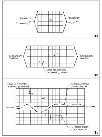
1D and 2D | 1D and 2D domains can be linked in three different ways. | ||
# A 2D domain within a 1D domain (1a) | # A 2D domain within a 1D domain (1a) | ||
# 1D elements representing culverts or pipe networks (1b or 1c) | # 1D elements representing culverts or pipe networks (1b or 1c) | ||
| Line 12: | Line 12: | ||
* Network coverage – Contains the 1D channels | * Network coverage – Contains the 1D channels | ||
* BC coverage – 1D Flow/2D Water Level Connection (HX) or Flow source from a 1D model (SX) arcs define the interface between the 1D and 2D domains. | * BC coverage – 1D Flow/2D Water Level Connection (HX) or Flow source from a 1D model (SX) arcs define the interface between the 1D and 2D domains. | ||
* 1D/2D Connections – Arcs connect 1D nodes to ends of 1D | * 1D/2D Connections – Arcs connect 1D nodes to ends of 1D flow/2D water Level arcs or flow source arcs. When used with flow source arcs only 1 connection arc is needed where the 1D Flow/2D Water Level arcs require 2 arcs (one to each end of the arc). | ||
Arcs in the connections coverage must snap to the 1D network nodes and the endpoints of the 1D | Arcs in the connections coverage must snap to the 1D network nodes and the endpoints of the 1D flow/2D water level connection arcs. The snapping option setup in the ''Map'' tab of the [[SMS:Preferences|''Preferences'' dialog]] should be used to ensure that the nodes are placed correctly. | ||
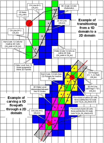
The following image shows how 1D/2D linkages are setup both for items 1 and 3 above. | The following image shows how 1D/2D linkages are setup both for items 1 and 3 above. | ||
Revision as of 14:46, 25 September 2017
1D and 2D domains can be linked in three different ways.
- A 2D domain within a 1D domain (1a)
- 1D elements representing culverts or pipe networks (1b or 1c)
- 1D cross-section based domain for river channel and 2D domain for floodplain (1c)
Linking 1D Pipe network within a 2D network
The easiest way to link a 1D pipe network to a 2D network is to double-click on one of the nodes in the network coverage and define an inlet (connection to the 2D domain). The inlet can be circular or rectangular and the shape and losses can be specified.
Linking 1D domain and 2D domains
Except for pipe networks defined above, linking a 1D network to a 2D network requires several coverages.
- Network coverage – Contains the 1D channels
- BC coverage – 1D Flow/2D Water Level Connection (HX) or Flow source from a 1D model (SX) arcs define the interface between the 1D and 2D domains.
- 1D/2D Connections – Arcs connect 1D nodes to ends of 1D flow/2D water Level arcs or flow source arcs. When used with flow source arcs only 1 connection arc is needed where the 1D Flow/2D Water Level arcs require 2 arcs (one to each end of the arc).
Arcs in the connections coverage must snap to the 1D network nodes and the endpoints of the 1D flow/2D water level connection arcs. The snapping option setup in the Map tab of the Preferences dialog should be used to ensure that the nodes are placed correctly.
The following image shows how 1D/2D linkages are setup both for items 1 and 3 above.
Related Topics
SMS – Surface-water Modeling System | ||
|---|---|---|
| Modules: | 1D Grid • Cartesian Grid • Curvilinear Grid • GIS • Map • Mesh • Particle • Quadtree • Raster • Scatter • UGrid |  |
| General Models: | 3D Structure • FVCOM • Generic • PTM | |
| Coastal Models: | ADCIRC • BOUSS-2D • CGWAVE • CMS-Flow • CMS-Wave • GenCade • STWAVE • WAM | |
| Riverine/Estuarine Models: | AdH • HEC-RAS • HYDRO AS-2D • RMA2 • RMA4 • SRH-2D • TUFLOW • TUFLOW FV | |
| Aquaveo • SMS Tutorials • SMS Workflows | ||

