GMS:Toolbars: Difference between revisions
No edit summary |
No edit summary |
||
| Line 47: | Line 47: | ||
|- | |- | ||
| align = "center" | [[Image:tool_measure.png]] || Measure || | | align = "center" | [[Image:tool_measure.png]] || Measure || | ||
{{Version GMS | {{Version GMS 9.0}} | ||
The Measure tool provides a quick way to measure distances. | The Measure tool provides a quick way to measure distances. | ||
*The tool is only available in plan view. | *The tool is only available in plan view. | ||
Revision as of 17:32, 26 April 2012
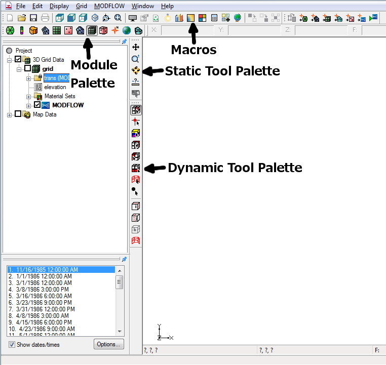
There are several Tool Palettes that can be displayed in the GMS interface. Below are the tool palettes that are on by default.
Macros
Many of the more frequently used menu commands can be accessed through the macro buttons. These buttons essentially serve as shortcuts to menu commands.
Static Tool Palette
The Static Tool palette contains the tools which are available in every module. These tools are tools for basic operations such as panning and zooming. Only one tool is active at any given time. The action that takes place when the user clicks in the Graphics Window depends on the current tool. The following table describes the tools in the Static Tool palette.
| Tool | Tool Name | Description | |||
|---|---|---|---|---|---|
| File:Tool Pan.GIF | Pan | The Pan tool is used to pan the viewing area of the Graphics Window. Panning can be done in 3 ways:
| |||
| File:Tool Zoom.GIF | Zoom | The viewing area can be magnified/shrunk using the Zoom tool. Zooming can be done in the following ways:
| |||
| File:Tool Rotate.GIF | Rotate | The Rotate tool provides a quick way to rotate the viewing location. Rotating can be done in the following ways:
| |||
| File:Tool measure.png | Measure |
The Measure tool provides a quick way to measure distances.
|
Dynamic Tool Palette
When the active module is changed by selecting an object in the Project Explorer, the tools in the Dynamic Tool Palette change to the set of tools associated with the selected object/module. Each module has a separate set of tools.
Mini-Grid Plot
The Mini-Grid Plot appears when a 3D grid is in memory and is activated when the orthogonal viewing mode is active. In the orthogonal mode, the viewing angle is always parallel to one of the three grid axes (I, J, or K) and only one of the rows, columns, or layers is displayed at one time. The Mini-Grid Plot shows an idealized representation of the 3D grid and shows which of the rows, columns, or layers is currently being displayed. The current row, column, or layer can be changed using the arrows just below the Mini-Grid Plot.
| This contains information about functionality available starting at GMS version 8.0. The content may not apply to other versions. |
Mini-Grid Toolbar
The Mini-Grid Toolbar appears when a 3D grid is in memory and is activated when the orthogonal viewing mode is active. In the orthogonal mode, the viewing angle is always parallel to one of the three grid axes (I, J, or K) and only one of the rows, columns, or layers is displayed at one time. The Mini-Grid Toolbar shows an idealized representation of the 3D grid and shows which of the rows, columns, or layers is currently being displayed. The current row, column, or layer can be changed using the arrows just below the Mini-Grid Toolbar.
Module Palette
The Module Palette is used to switch between modules. Only one module is active at any given time. However, the data associated with a module (ex. a 3D finite element mesh) is preserved when the user switches to a different module. Activating a module simply changes the set of available tools and menu commands.
See also
GMS – Groundwater Modeling System | ||
|---|---|---|
| Modules: | 2D Grid • 2D Mesh • 2D Scatter Point • 3D Grid • 3D Mesh • 3D Scatter Point • Boreholes • GIS • Map • Solid • TINs • UGrids | |
| Models: | FEFLOW • FEMWATER • HydroGeoSphere • MODAEM • MODFLOW • MODPATH • mod-PATH3DU • MT3DMS • MT3D-USGS • PEST • PHT3D • RT3D • SEAM3D • SEAWAT • SEEP2D • T-PROGS • ZONEBUDGET | |
| Aquaveo | ||
