SMS:SRH-2D Plots: Difference between revisions
| Line 9: | Line 9: | ||
** 0% means the same amount of flow exited during this time step as entered | ** 0% means the same amount of flow exited during this time step as entered | ||
** >0% means more flow left the simulation than entered it. | ** >0% means more flow left the simulation than entered it. | ||
* ''Mass Balance'' – | * ''Mass Balance'' – Includes mass loss -vs- time and average mass loss -vs- time | ||
* ''Monitor Points WSE'' – Monitor point water level -vs- time. Will display one plot for each monitor point in the simulation. | * ''Monitor Points WSE'' – Monitor point water level -vs- time. Will display one plot for each monitor point in the simulation. | ||
* ''Monitor Points Z'' – Monitor point ground level -vs- time. Will display one for each monitor point in the simulation. This plot is not meaningful unless the simulation includes sediment transport. | * ''Monitor Points Z'' – Monitor point ground level -vs- time. Will display one for each monitor point in the simulation. This plot is not meaningful unless the simulation includes sediment transport. | ||
| Line 15: | Line 15: | ||
Under the plot list, there is the following option: | Under the plot list, there is the following option: | ||
*''Specify time range'' – | *''Specify time range'' – Allows specifying the time range of the plot to be viewed. The possible range will be 0 to the length (time in hours) of the simulation. | ||
**''Minimum time'' – The beginning time range. | **''Minimum time'' – The beginning time range. | ||
**''Maximum time'' – The ending time range. | **''Maximum time'' – The ending time range. | ||
{{-}} | {{-}} | ||
==Monitor and Structure Plots== | ==Monitor and Structure Plots== | ||
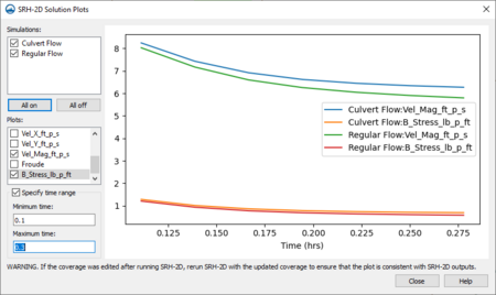
[[File:SRH2D SolutionPlots.png|thumb|450 px|Example of the ''SRH-2D Solution Plots'' dialog for an SRH-2D structure]] | [[File:SRH2D SolutionPlots.png|thumb|450 px|Example of the ''SRH-2D Solution Plots'' dialog for an SRH-2D structure]] | ||
Revision as of 16:54, 29 April 2021
SMS proved some tools to quickly generate plots from the solution of a successful SRH-2D model run.
Simulation Plots
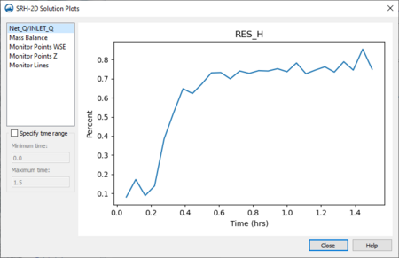
In the SRH-2D simulation right-click menu, using the Tools | View Simulation Plots command brings up the SRH-2D Solution Plots dialog. This dialog provides a list of solution plots that were generated during the model run. The list of available plots in on the left side of the dialog. Once a plot is selected from the list, the plot will be shown in the plot window on the right side of the dialog.
Available plots include:
- Net_Q/INLET_Q – Net Q -vs- time. Percentage of flow entering the simulation that leaves the simulation at a given time:
- -100% means all the flow that entered the simulation at this time stayed in the simulation
- 0% means the same amount of flow exited during this time step as entered
- >0% means more flow left the simulation than entered it.
- Mass Balance – Includes mass loss -vs- time and average mass loss -vs- time
- Monitor Points WSE – Monitor point water level -vs- time. Will display one plot for each monitor point in the simulation.
- Monitor Points Z – Monitor point ground level -vs- time. Will display one for each monitor point in the simulation. This plot is not meaningful unless the simulation includes sediment transport.
- Monitor Lines – Monitor line flux vs time. Will display one plot for each monitor line in the simulation.
Under the plot list, there is the following option:
- Specify time range – Allows specifying the time range of the plot to be viewed. The possible range will be 0 to the length (time in hours) of the simulation.
- Minimum time – The beginning time range.
- Maximum time – The ending time range.
Monitor and Structure Plots
SMS can generate a solution plot at a monitoring location or at a structure location. The plot will use the solution datasets generated during the model run. If the coverage was edited after running SRH-2D, rerun SRH-2D with the updated coverage to ensure that hte plot is consistant with the SRH-2D outputs.
For a monitoring point or line, in the monitor coverage, select the monitoring point or line then right-click and select the Monitor Points Plot or Monitor Lines Plot command to open the SRH-2D Solution Plots dialog for a monitor location. Note that the monitor coverage must have been included in the simulation model run. Also note that only one point or line can be selected
For an SRH-2D structure, in the boundary conditions coverage, select the structure arcs then right-click and select the Structure Output Plots command to open the SRH-2D Solution Plots dialog for SRH-2D structures. Only one structure arc can be selected to access the structure plots.
The SRH-2D Solution Plots dialog is similar for both monitor points or lines, and SHR-2D strucutes. The dialog has the following options.
- Simulations – Contains a list of all available simulations where the monitor coverage or boundary conditions coverage was included during the simulation run. Select which of these simulations to include in the plot.
- All on – Select to include all available simulations in the plot.
- All off – Select to remove all simulations from the plot.
- Plots – Contains a list of all available solution datasets from the model run. Selected datasets will appear in the plot.
- Specify time range – Allows specifying the time range of the plot to be viewed. The possible range will be 0 to the length (time in hours) of the simulation.
- Minimum time – The beginning time range.
- Maximum time – The ending time range.
Related Topics
| [hide] SMS – Surface-water Modeling System | ||
|---|---|---|
| Modules: | 1D Grid • Cartesian Grid • Curvilinear Grid • GIS • Map • Mesh • Particle • Quadtree • Raster • Scatter • UGrid |  |
| General Models: | 3D Structure • FVCOM • Generic • PTM | |
| Coastal Models: | ADCIRC • BOUSS-2D • CGWAVE • CMS-Flow • CMS-Wave • GenCade • STWAVE • WAM | |
| Riverine/Estuarine Models: | AdH • HEC-RAS • HYDRO AS-2D • RMA2 • RMA4 • SRH-2D • TUFLOW • TUFLOW FV | |
| Aquaveo • SMS Tutorials • SMS Workflows | ||

