SMS:Scatter Options: Difference between revisions
| Line 18: | Line 18: | ||
==Triangulation Optimization Options== | ==Triangulation Optimization Options== | ||
When the optimize triangulation command is invoked, the triangles are optimized in one of | Optimizing triangles can useful when the point spacing is inconsistent either longitudinally (along a feature such as a channel or an embankment) or when the data is quite sparse. This command is not recommended for high resolution or densely packed TINs. When the optimize triangulation command is invoked, the triangles are optimized in one of three ways: | ||
* '' | * ''Minimize Angles Optimization'' – The triangles are swapped to conform to the Delaunay Criterion. | ||
* ''Area Optimization'' | * ''Minimize Area Ratio Optimization'' – The triangles are swapped to result in triangles of equal area. This approach was developed specifically to attempt to honor cross sectional surveys. It can be noted that cross section data is not uniformly sampled. Generally the point in a single cross section are much closer to each other than they are to points in another cross section. This observation has led to the development of many functions for importing and working with cross sections. See [[SMS:Cross_Section_Notes | Cross Section Notes]] and the cross section tutorials for more information. For this triangulation optimization option, the observation is applied by noting that triangles formed by connecting three vertices in a single cross section will generally be much smaller than triangles that connect two cross sections. When this option is selected, and the '''Optimize Triangulation''' command is issued (from the '''Triangles''' menu), SMS compares the area of one triangle to its neighbor. If the area of the smaller triangle is less than the area of the larger triangle divided by the specified bias, the triangles are swapped. This approach is also useful for linear side scan surveys. | ||
* ''Contour Optimization'' – | * ''Smooth Contour Optimization'' – This option is extremely experimental and should be used with care. It is much slower than the other methods and should not be used when more than a few hundred edges are being optimized. Even more than the other two options, it should not be used for regularly distributed scatter sets. It was developed from the observation that when a modeler desires to represent a feature in a TIN, and creates breaklines to edit the TIN, it is often useful to follow the centerline of a feature such as a thaleg, roadway centerline or channel bank. It can be noted that in these situations, the breakline often connects points of similar elevation/value. The smooth contour optimization command loops through the edges in the TIN and swaps the edge if the swapped edge has a smaller slope than the existing edge. Results can be very erratic, and the method is subject to change at any time. | ||
[[Image:Triangulation_optimization.jpg|thumb|none|left|500 px|Area optimization example.]] | [[Image:Triangulation_optimization.jpg|thumb|none|left|500 px|Area optimization example.]] | ||
Latest revision as of 22:45, 24 May 2022
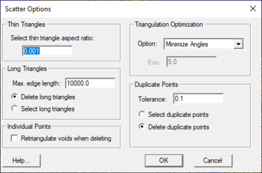
The Scatter Options dialog is accessed through the Scatter Options command in the Scatter menu of the scatter module.
Triangulation Options
This section adjusts the maximum aspect ratio of a thin triangle. The aspect ratio is the ratio of the triangle width to the triangle height. All triangles with an aspect ratio less than what is specified are considered thin.
Long Triangles
This section contains options for deleting or selecting long triangles. The Max Edge Length option determines the longest length that can be allowed. Triangles with lengths longer than this will be selected when using the Select Long Triangles command.
Individual Points
This section contains the Retriangulate voids when deleting option. When scatter points are deleted, the triangles attached to the scatter points (if any) are also deleted. If this option is on, surrounding triangles are retriangulated to fill the void.
When deleting selected scatter vertices, if the vertex count exceeds ~1000 there will be a noticeable delay if the Retriagulate voids when deleting box is checked.
Triangulation Optimization Options
Optimizing triangles can useful when the point spacing is inconsistent either longitudinally (along a feature such as a channel or an embankment) or when the data is quite sparse. This command is not recommended for high resolution or densely packed TINs. When the optimize triangulation command is invoked, the triangles are optimized in one of three ways:
- Minimize Angles Optimization – The triangles are swapped to conform to the Delaunay Criterion.
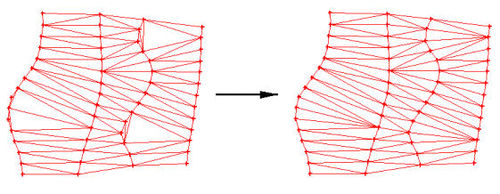
- Minimize Area Ratio Optimization – The triangles are swapped to result in triangles of equal area. This approach was developed specifically to attempt to honor cross sectional surveys. It can be noted that cross section data is not uniformly sampled. Generally the point in a single cross section are much closer to each other than they are to points in another cross section. This observation has led to the development of many functions for importing and working with cross sections. See Cross Section Notes and the cross section tutorials for more information. For this triangulation optimization option, the observation is applied by noting that triangles formed by connecting three vertices in a single cross section will generally be much smaller than triangles that connect two cross sections. When this option is selected, and the Optimize Triangulation command is issued (from the Triangles menu), SMS compares the area of one triangle to its neighbor. If the area of the smaller triangle is less than the area of the larger triangle divided by the specified bias, the triangles are swapped. This approach is also useful for linear side scan surveys.
- Smooth Contour Optimization – This option is extremely experimental and should be used with care. It is much slower than the other methods and should not be used when more than a few hundred edges are being optimized. Even more than the other two options, it should not be used for regularly distributed scatter sets. It was developed from the observation that when a modeler desires to represent a feature in a TIN, and creates breaklines to edit the TIN, it is often useful to follow the centerline of a feature such as a thaleg, roadway centerline or channel bank. It can be noted that in these situations, the breakline often connects points of similar elevation/value. The smooth contour optimization command loops through the edges in the TIN and swaps the edge if the swapped edge has a smaller slope than the existing edge. Results can be very erratic, and the method is subject to change at any time.
TIN Contour Optimization
Description It is known that a global optimum triangle configuration exists for any given set of scatter points. The qualitative accuracy of that global optimum will vary depending on the density of the available data. Despite its existence, there is no guarantee that a progressive edge-swap process, such as the one used by the contour optimization option, will converge to that global optimum. The likelihood that a global optimum will result varies inversely with the size of the dataset. The contour smoothing algorithm will assuredly converge to a sub-optimum configuration and the smaller the dataset, the more closely the result with approximate the global optimum. As demonstrated by this relationship, the contour smoothing algorithm works very well for discovering local optimums.
Contour Optimization Usage Guidelines
The following are recommended guidelines for getting the most efficacy out of the contour optimization option.
- Break down large datasets into smaller areas for optimization by selecting an area with the triangle selection tool before optimizing. This also has the benefit of decreasing the optimization runtime for the entire dataset.
- Recognize that the more edges a contour deviation spans, the less likely it is that the optimization will correct the problem. It is recommended that large deviations, such as can be easily identified, be minimized by the insertion of appropriately forced breaklines prior to optimization.
- A better optimization can be obtained for large datasets if locally selected optimization areas are chosen so as to overlap each other.
- This progressive edge-swap optimization is sensitive to initial conditions. Often by varying the initial triangulation (Delaunay, Area Bias or hybrid of both) a better optimization can be achieved.
By following these guidelines, the time spent identifying minor changes and swapping edges individually is greatly minimized. Please note that this optimization is iterative and larger data selections will not only require longer runtime but are also more likely to converge to any number of sub-optima dependent on the specific configuration of the triangles. This recommended process of user guided optimization is likely to require some repetition but proves to be much more time efficient.
The following are some of the scenarios under which contour optimization is especially useful.
- Smoothing of channel banks.
- Refining topographical transitions between flat and steep areas.
- Streamlining jagged contours and contour jumps caused by triangulation.
- Connecting thalweg points between cross-sections.
In addition, the following are known limitations of the contour smoothing algorithm.
- Will not define small dams in narrow channels because of the indeterminate nature of the scatter point data.
- Large contour discontinuities and displacements that require the swapping of many edges in a sequential manner, without decreasing the departure angle, before achieving an optimum configuration are unlikely to resolve themselves using this method. It is recommended to insert breaklines to connect the proper points and force them prior to optimizing the area.
- Channel cross sections that are inset into higher resolution scatter sets will result in unacceptable triangulation along the banks if triangulated together. It is recommended to either triangulate and optimize the cross-section scatter set separately and then merge the two together while preserving the cross-section set’s triangulation, or, add and force breaklines connecting the endpoints of the cross sections to better approximate the optimum before attempting to optimize.
- Be aware that large datasets, if optimized in their entirety, are likely to take excessive amounts of time to run. It is recommended to manually select smaller areas of large datasets to run incrementally and work through the dataset in this manner. This method of user guided optimization drastically decreases the runtime required to optimize large datasets and allows bypassing any areas believed to have acceptable triangulation.
Duplicate Vertex Options
When the Select/Delete Duplicate Points menu item is selected, points within a tolerance of other points are selected or deleted. Sets the Tolerance and whether to delete or select the points when the command is invoked.
Related Topics
SMS – Surface-water Modeling System | ||
|---|---|---|
| Modules: | 1D Grid • Cartesian Grid • Curvilinear Grid • GIS • Map • Mesh • Particle • Quadtree • Raster • Scatter • UGrid |  |
| General Models: | 3D Structure • FVCOM • Generic • PTM | |
| Coastal Models: | ADCIRC • BOUSS-2D • CGWAVE • CMS-Flow • CMS-Wave • GenCade • STWAVE • WAM | |
| Riverine/Estuarine Models: | AdH • HEC-RAS • HYDRO AS-2D • RMA2 • RMA4 • SRH-2D • TUFLOW • TUFLOW FV | |
| Aquaveo • SMS Tutorials • SMS Workflows | ||

