SMS:Curvilinear Grid Display Options: Difference between revisions
From XMS Wiki
Jump to navigationJump to search
No edit summary |
No edit summary |
||
| Line 5: | Line 5: | ||
*'''Contours''' – Contours are drawn for the active scalar dataset. Use the contours tab to change [[SMS:Contour Options|contour options]]. | *'''Contours''' – Contours are drawn for the active scalar dataset. Use the contours tab to change [[SMS:Contour Options|contour options]]. | ||
*'''Boundary''' – A line is drawn around the perimeter of the curvilinear grid. | *'''Boundary''' – A line is drawn around the perimeter of the curvilinear grid. | ||
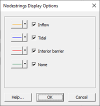
*'''Nodestring''' – Determines the color of nodestring lines. The '''Options''' button will bring up the ''Nodestrings Display Options'' dialog where colors can be selected for varying nodestring types. [[File:CurvNodestringDisplay.jpg|thumb| | *'''Nodestring''' – Determines the color of nodestring lines. The '''Options''' button will bring up the ''Nodestrings Display Options'' dialog where colors can be selected for varying nodestring types. [[File:CurvNodestringDisplay.jpg|thumb|200 px|Example of the ''Nodestrings Display Options'' dialog.]] | ||
*'''Element Fill''' – Elements can be filled using the following options: | *'''Element Fill''' – Elements can be filled using the following options: | ||
<blockquote> | <blockquote> | ||
Revision as of 18:31, 13 October 2014
File:SMS Display Curvilinear Grid.jpg
Display Options dialog showing Curvilinear Grid options
The properties of the curvilinear grid data SMS displays on the screen can be controlled through the Display Options dialog. The entities associated with the curvilinear grid module with display options are shown below. Some of these entities also have an associated Options button. For these entities, additional display options are available. The available curvilinear grid display options include the following:
- Nodes – A circle is filled around each node. The user can specify the radius and color of these circles. The Options button is used to set the display of nodal boundary condition data. The dialog that opens when this button is clicked depends on the current numerical model.
- Edges – Cell edges.
- Contours – Contours are drawn for the active scalar dataset. Use the contours tab to change contour options.
- Boundary – A line is drawn around the perimeter of the curvilinear grid.
- Nodestring – Determines the color of nodestring lines. The Options button will bring up the Nodestrings Display Options dialog where colors can be selected for varying nodestring types.
- Element Fill – Elements can be filled using the following options:
- None
- Materials – Elements are filled using the material assigned to the element.
- Mesh quality – Elements are filled using a user specified mesh quality metric. For a description of the mesh quality metrics, please see the VERDICT Manual which contains the mathematical definition of each quality metric. The VERDICT website contains further information on the VERDICT mesh verification code library.
- Solid color – Elements are filled using a solid color.
- Texture mapping – An image is draped over the mesh elements.
Model Specific Options
Each model may include model specific display options. These appear at the bottom of the display options dialog.
Related Topics
SMS – Surface-water Modeling System | ||
|---|---|---|
| Modules: | 1D Grid • Cartesian Grid • Curvilinear Grid • GIS • Map • Mesh • Particle • Quadtree • Raster • Scatter • UGrid |  |
| General Models: | 3D Structure • FVCOM • Generic • PTM | |
| Coastal Models: | ADCIRC • BOUSS-2D • CGWAVE • CMS-Flow • CMS-Wave • GenCade • STWAVE • WAM | |
| Riverine/Estuarine Models: | AdH • HEC-RAS • HYDRO AS-2D • RMA2 • RMA4 • SRH-2D • TUFLOW • TUFLOW FV | |
| Aquaveo • SMS Tutorials • SMS Workflows | ||
