GMS:Borehole Cross Sections: Difference between revisions
(update image) |
(update image) |
||
| Line 48: | Line 48: | ||
| align = "center" | [[Image:Tool_CreateArc.gif]] || '''Create Arc''' || Creates arcs between two nodes or vertices within the cross section | | align = "center" | [[Image:Tool_CreateArc.gif]] || '''Create Arc''' || Creates arcs between two nodes or vertices within the cross section | ||
|- | |- | ||
| align = "center" | [[ | | align = "center" | [[File:Pan static tool.png]] || '''Pan''' || Pans in the viewing area of the Graphics Window | ||
|- | |- | ||
| align = "center" | [[File:Zoom tool.png]] || '''Zoom''' || Magnifies or shrinks the current viewing area | | align = "center" | [[File:Zoom tool.png]] || '''Zoom''' || Magnifies or shrinks the current viewing area | ||
Revision as of 20:52, 20 October 2015
A borehole cross section is a set of polylines and polygons that define the stratigraphy between two boreholes. A borehole cross section can be created manually or automatically.
Contents
Creation
Automatic creation
Cross sections can be created automatically using the Boreholes | Auto-Create Blank Cross Sections menu command. This uses a triangulation process to determine the most likely connections between boreholes. The top and/or bottom arcs of the new cross sections can be warped to match the elevation of TIN surfaces using the Snap Cross Sections to TIN dialog which appears when the Boreholes | Auto-Create Blank Cross Sections command is executed. Snapping the tops and bottoms of cross sections to TIN surfaces can also be done at any time via the Boreholes | Advanced | Snap Cross Sections to TIN menu command. Keep in mind, however, that warping the top and bottom of a cross section may interfere with the internal polygons that are defined in the cross section, so snapping to a TIN is best done before filling in the cross sections.
Manual creation
Cross sections can be created manually by using the Create Cross Section tool and clicking on boreholes.
Editing
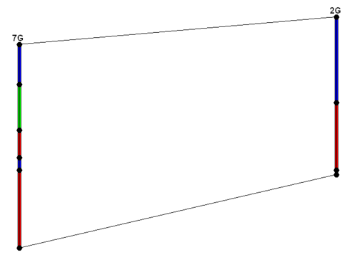
When a borehole cross section is first created, it is made up of a set of default lines. The figure below shows a default cross section. Notice that "arcs" (polylines) have been created defining the top and bottom of the cross section and an "arc" (polyline) has been created for each segment in the boreholes.
Automatic editing
The Boreholes | Auto-Fill Blank Cross Sections menu command can be used to automatically fill in all existing blank cross sections. The command can use either the horizon IDs (preferred) or materials information on the boreholes.
Manual editing
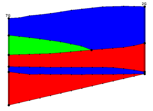
To edit a cross section manually, the user must use the Select Cross Section tool and select a cross section. The Cross Section Editor dialog can be then opened by selecting the Cross Section Editor command from the Borehole menu while the user has either a single or a series of cross sections selected. The user can also launch the Cross Section Editor dialog by double-clicking on a single cross section. The next figure shows a finished cross section.
Restrictions
GMS imposes the following restrictions on cross sections that should be kept in mind when editing:
- All polygons must be connected to boreholes
- All arcs must connect to borehole contacts
Borehole Cross Section Editor
The Cross Section Editor can be used to manually construct and view cross sections between boreholes. The Cross Section Editor in GMS 6.5 has been updated to allow for the display and editing of multiple borehole cross sections. The Cross Section Editor has a set of tools and toggles used to create, edit, and view the cross sections. The tools used to create the nodes, polylines, and polygons are similar to the tools available in the Map module used to create feature objects (points, arcs, and polygons). The following tables describe the tools and display options available in the Cross Section Editor.
Tools
| Tool | Tool Name | Description |
|---|---|---|
| File:Select Object.bmp | Select Tool | Generic selection tool that selects nodes, vertices, arcs, and polygons |
| File:Tool SelectNode.gif | Select Point/Node | Selection tool that will only select points or nodes |
| File:Tool SelectVertex.gif | Select Vertex | Selection tool that will only select vertices |
| File:Tool SelectArc.gif | Select Arc | Selection tool that will only select arcs |
| File:Tool SelectPoly.gif | Select Polygon | Selection tool that will only select polygons |
| File:Tool CreateVertex.gif | Create Vertex | Creates new vertices along arcs within the cross section |
| File:Tool CreateArc.gif | Create Arc | Creates arcs between two nodes or vertices within the cross section |
| Pan | Pans in the viewing area of the Graphics Window | |
| Zoom | Magnifies or shrinks the current viewing area | |
| File:Tool FrameAllXSects.GIF | Frame All Cross Sections | Frames to the extents of all the cross sections |
| File:Tool FrameCurrentXSect.GIF | Frame Current Cross Section | Frames to the extents of the current cross section |
| File:Tool ZMagnification.GIF | Z-Magnification | Adjusts the Z-Magnification factor to increase or decrease the graphical display along the Y (real world Z) axis, making more or less room at the top and bottom of the screen while maintaining the boreholes and cross sections in the middle of the screen |
| File:Tool PlotOptions.GIF | Plot Options | Adjusts the axes plot options, including: title, background color, font, font color, grid display, axes titles, and axes display |
| File:Tool Delete.GIF | Delete | Deletes the currently selected vertices, nodes, arcs, or polygons |
| File:Tool Left.GIF | Left | Activates the cross section to the left of the current cross section as the current cross section |
| File:Tool Right.GIF | Right | Activates the cross section to the right of the current cross section as the current cross section |
| Prints the current Graphics Window | ||
| File:Tool AutoMatch.GIF | Auto-Match Cross Section | Creates a set of straight arcs connecting matching contacts on adjacent boreholes based on the user's selection to use Horizons or Materials |
| File:Tool CreatePoly.GIF | Build Cross Section Polygons | Deletes all current polygons, builds new polygons using all of the arcs, and checks to see if every polygon built is valid. A polygon is valid only if it contains either one arc representing a borehole region or two arcs representing two matching borehole regions on two holes. Thus, every valid polygon can be assigned one and only one material type. If every polygon built is valid, the Color Fill toggle will be automatically turned on and all polygons built will be filled with the color representing the material they are assigned. Otherwise, a dialog saying "Invalid polygons present" will pop up and all polygons built will be deleted. |
| File:Tool DeleteAll.GIF | Delete All | Deletes all of the vertices, nodes, arcs, and polygons in the current cross section |
Display Options
| Display Toggle | Description | ||
|---|---|---|---|
| Nodes | Controls the display of the nodes in the graphics window | ||
| Vertices | Controls the display of the vertices in the graphics window | ||
| Arcs | Controls the display of the arcs in the graphics window | ||
| Boreholes | Controls the display of the arcs in the graphics window | ||
| Poly fill | Controls the display of the polygons in the graphics window | ||
| Mirror view | Reverses the order in which the cross sections are displayed | ||
| Mark inactive | Dims the inactive cross sections | ||
| Display axes | Controls the display of the plot axes in the graphics window | ||
| |||
| Axes behind | When checked, the axes are drawn behind the cross section. When unchecked, the axes are drawn on top of the cross section. | ||
| Material legend | Controls the display of the material legend |
| [hide]GMS – Groundwater Modeling System | ||
|---|---|---|
| Modules: | 2D Grid • 2D Mesh • 2D Scatter Point • 3D Grid • 3D Mesh • 3D Scatter Point • Boreholes • GIS • Map • Solid • TINs • UGrids | |
| Models: | FEFLOW • FEMWATER • HydroGeoSphere • MODAEM • MODFLOW • MODPATH • mod-PATH3DU • MT3DMS • MT3D-USGS • PEST • PHT3D • RT3D • SEAM3D • SEAWAT • SEEP2D • T-PROGS • ZONEBUDGET | |
| Aquaveo | ||


