SMS:SRH-2D Structures
SRH-2D has the capability to model hydraulic structures including: bridges, culverts, gates, and weirs.
The structure boundary conditions were added to the SRH-2D model at the request of FHWA in 2015 and included in the interface for SMS 12.0. General structure requirements include:
- Each structure is specified by selecting two arcs which represent the upstream and downstream faces of the structure.
- The two arcs must be ordered in the same direction (i.e. left to right as looking downstream). If this is not the case, model results are will not represent the structure.
- In the region of structures that represent one dimensional flow (Weir, Culvert, Gate) the two dimensional flow is disabled. SRH-2D will identify cells/elements enclosed by the upstream and downstream structure definitions (connecting the end points of the arcs/nodestrings) and disable the elements. In order to make the display in SMS match what the model is doing, the user will generally create this polygon in the material coverage and assign the area to the disabled material type.
Culvert
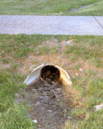
A structure that allows water to flow under a road, railroad, trail, or similar obstruction. SRH-2D can make use of culvert structures by coupling with the Federal Highway Administrations HY-8 culvert analysis application.
Specific guidelines include:
- It is necessary to specify a file (path and name) where all HY-8 crossing definitions used in this boundary condition coverage are stored. This is accessed by right-clicking on the coverage and selecting HY-8 Options.
- It is necessary to define the crossing before running SRH-2D. This is done by creating two arcs representing the upstream and downstream portion of the culvert then assigning the both arcs the "Culvert" Type in the Linear BC dialog. The crossing definition can be accessed in the boundary condition dialog after assigning the arcs to be a culvert.
- HY-8 computes flow both through the culvert and over the road/weir above the culvert. Attributes are specified in the crossing definition.
The boundary conditions options for culvert arcs include:
- Object Role – Allows assigning each arc to be either "culvert upstream" or "culvert downstream".
- Units for HY-8 Display
- Launch HY-8 – Starts the HY-8 software and opens the culvert file that was specified in the coverage Options dialog.
Gate
Gate structures can simulate both overflow and underflow gates. Adding a gate structure to the boundary conditions coverage requires creating two arcs and assigning both the arcs the "Gate" Type in the Linear BC dialog.
The boundary conditions options for gate arcs include:
- Object Role – Allows assigning each arc to be either "gate upstream" or "gate downstream".
- Units – Can select feet or meters.
- Crest Elevation
- Height of Gate Opening
- Width of Gate Opening
- Contract Coefficient with Underflow Orifice
- Type – Allows assigning "paved", "gravel", "single", "double", "sharp", "broad", or "user" defined.
Pressure Flow Bridge
A bridge can be represented as a pressure flow boundary condition in SMS.
- The pressure zone definition defines a ceiling elevation that can vary linearly from the upstream arc to the downstream arc. This could also be side to side if the arcs are defined as the sides of the bridge instead of upstream/downstream. More complex ceiling elevation variation can be simulated using multiple pairs of pressure flow arcs.
- The pressure zone cannot touch any mesh/grid boundaries nor can voids in the mesh be defined in the pressure zone.
- Pressure zones do not allow any overtopping.
The boundary conditions options for pressure flow arcs include:
- Object Role – Allows assigning each arc to be either "gate upstream" or "gate downstream".
- Units – Can select feet or meters.
- Ceiling elevation along upstream
- Ceiling elevation along downstream
- Manning roughness coefficient between water and ceiling
Weir
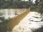
A barrier across a river designed to alter its flow characteristics. In SMS, a weir can be represented as two arcs. One arc represents the upstream face of the weir structure and the other represents the downstream face of the weir.
Typically a weir would be represented in the geometry of the mesh/grid. One application of the weir structure would be to quickly investigate the impact of inserting a weir with a variety of crest elevations (designing the structure). In this case, the same grid/mesh could be used for all simulations.
The boundary conditions options for weir arcs include:
- Object Role – Allows assigning each arc to be either "gate upstream" or "gate downstream".
- Units – Can select feet or meters.
- Crest elevation
- Length of weir
- Type – Allows assigning the following:
- Paved roadway – flow over a roadway embankment with a paved surface
- Gravel roadway – flow over a roadway embankment with a gravel surface
- Single railroad track – flow over a railroad track embankment with one set of rails
- Double railroad track – flow over a railroad track embankment with two sets of rails
- Sharp crested weir – flow over a sharp crested weir
- Broad crested weir – flow over a broad crested weir
- User defined – flow over a user defined weir
Related Topics
SMS – Surface-water Modeling System | ||
|---|---|---|
| Modules: | 1D Grid • Cartesian Grid • Curvilinear Grid • GIS • Map • Mesh • Particle • Quadtree • Raster • Scatter • UGrid |  |
| General Models: | 3D Structure • FVCOM • Generic • PTM | |
| Coastal Models: | ADCIRC • BOUSS-2D • CGWAVE • CMS-Flow • CMS-Wave • GenCade • STWAVE • WAM | |
| Riverine/Estuarine Models: | AdH • HEC-RAS • HYDRO AS-2D • RMA2 • RMA4 • SRH-2D • TUFLOW • TUFLOW FV | |
| Aquaveo • SMS Tutorials • SMS Workflows | ||

