User:Jcreer/SMS:AdH Interface
AdH Coverages
The AdH interface includes a few map coverages. These map coverages are used to provide input for the AdH simulation. AdH use the following model specific coverages:
- Boundary Conditions
- Materials
- Sediment Materials
AdH Boundary Conditions
ADH boundary conditions consist of two specification types (Dirichlet and Natural) and three condition types (flow, pressure, and transport). Dirichlet data is applied on the domain to individual nodes or to groups of nodes (defined with nodestrings). Natural data (flux) is applied through edges of the domain defined by nodestrings and includes a friction specification. A node or nodestring can be assigned only one condition option from each of the three condition types (two flow conditions cannot be assigned to a single node).
The boundary conditions coverage for AdH allows assigning boundary condition attributes for both arcs and points.
Arc Attributes
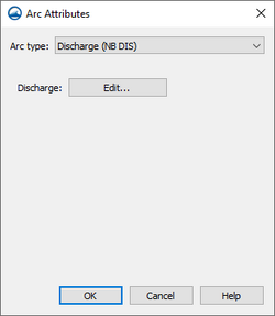
The Arc Attributes dialog is reached by right-clicking on an arc in the AdH boundary conditions and selecting the Assign Arc Attributes command. In the dialog, the Arc type option have several boundary condition attributes for the selected arc. The following Arc type options are as follows:
- "Off" – No attributes will be assigned to the arc.
- "Natural outflow (OB OF)" – allows flow out without any modification to flow properties. Can be specified on boundaries where the exact flow conditions are unknown.
- "Discharge (NB DIS)" – Applies subcritical inflow as a natural total discharge boundary condition.
- Discharge – Clicking Edit opens the XY Series Editor dialog where discharge values can be entered.
- "Flow (NB OVL)" – Applies inflow as a natural unit discharge boundary condition.
- Flow per unit area – Clicking Edit opens the XY Series Editor dialog where discharge values can be entered.
- "Water surface elevation (NB OTW)" – Links a particular time series of water surface elevation to the boundary condition.
- Elevation – Clicking Edit opens the XY Series Editor dialog where water surface elevation values can be entered.
- "Spillway (NB SPL)" – Specifies spillway flow.
- % flow out – Clicking Edit opens the XY Series Editor dialog where weir coefficient values can be entered.
- "Tidal boundary (NB TID)" – Indicates tidal constituents will be applied to the boundary.
- "Stage discharge boundary (NB SDR)" – Specifies a stage-discharge boundary.
- Coefficient – Specified constants for coefficients A–E.
- "Velocity and depth (DB OVH)" – Dirichlet boundary condition for supercritical flow.
- Snapping type – Defines how the boundary conditions are applied to mesh.
- "Point snap" – Applies the attributes to the mesh nodes or points upon export.
- "Edgestring snap" – Applies the attributes to the mesh element edge upon export.
- "Midstring snap" – Applies the attributes to the center of the mesh elements upon export.
- X velocity – Clicking Edit opens the XY Series Editor dialog where x-velocity values can be entered.
- Y velocity – Clicking Edit opens the XY Series Editor dialog where y-velocity values can be entered.
- Depth – Clicking Edit opens the XY Series Editor dialog where depth values can be entered.
- Snapping type – Defines how the boundary conditions are applied to mesh.
- "Stationary lid elevation (DB LDE)" – Allows assigning lid elevations to an arc.
- Snapping type
- Point snap
- Edgestring snap
- Midstring snap
- Elevation – Clicking Edit opens the XY Series Editor dialog where elevation values can be entered.
- Snapping type
- "Depth of water under stationary lid (DB LDH)" – Allows assigning lid depths to an arc.
- Snapping type
- Point snap
- Edgestring snap
- Midstring snap
- Depth – Clicking Edit opens the XY Series Editor dialog where depth values can be entered.
- Snapping type
- "Floating stationary object (DB LID)" – Allows assigning liddraft to an arc.
- Snapping type
- Point snap
- Edgestring snap
- Midstring snap
- Draft of lid – Clicking Edit opens the XY Series Editor dialog where draft values can be entered.
- Snapping type
Friction
Friction controls are used to compute estimated values of the friction induced by several types of bed roughness and linear roughness conditions.
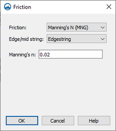
Friction can be applied to a feature arc by right-clicking on the arc and selecting the Assign Friction command. In the Friction dialog, specify the Friction type as one of the following options:
- "Off" – No friction will be applied to the arc.
- "Manning's N (MNG)" – Friction will be applied using Manning's n.
- Edge/mid string
- Edgestring
- Midstring
- Manning's n – Specify the value of Manning's n.
- Edge/mid string
- "Manning's Equation (MNC)" – Friction will be applied using the classic formulation Manning's n.
- Edge/mid string
- Edgestring
- Midstring
- Manning's n – Specify the value of Manning's n.
- Edge/mid string
- "Equivalent roughness height (ERH)" – Friction will be applied using equivalent sand roughness height.
- Edge/mid string
- Edgestring
- Midstring
- Roughness height – Enter a value for the equivalent sand roughness height.
- Edge/mid string
- "Submerged aquatic vegetation (SAV)" – Compute the drag coefficient associated with the bottom shear stress resulting from a steady current field over a bed consisting of submerged aquatic vegetation.
- Edge/mid string
- Edgestring
- Midstring
- Roughness height of canopy – Enter a value for the roughness height of the SAV canopy.
- Undeflected stem height – Enter a value for the undeflected stem height of the SAV.
- Edge/mid string
- "Un-submerged rigid vegetation (URV)" – Compute a shear stress coefficient for use in computing the bottom shear stress resulting from a steady current through rigid, unsubmerged vegetation.
- Edge/mid string
- Edgestring
- Midstring
- Bed roughness height – Enter a value for the bed roughness height.
- Average stem diameter – Enter a value for the average stem diameter.
- Average stem density – Enter a value for the average stem density.
- Edge/mid string
- "Equivalent drag obstructions (EDO)" – Computes a shear stress coefficient for use in computing the shear stress resulting from a steady current through or over an evenly distributed field of flow obstructions.
- Edge/mid string
- Edgestring
- Midstring
- Bed roughness height – Enter a value for the bed roughness height.
- Obstruction diameter – Enter a value for the average obstruction diameter.
- Obstruction height – Enter a value for the average obstruction height.
- Edge/mid string
- "Ice friction (ICE, IRH, BRH)" – Applies as a pressure field on the water surface to account for the effects that stationary ice on the water surface has on the flow below.
- Edge/mid string
- Edgestring
- Midstring
- Ice thickness
- Ice density – Enter a value for the density of ice.
- Ice movement
- Ice roughness height – Enter a value for the equivalent ice roughness height.
- Bed roughness height – Enter a value for the equivalent bed roughness height.
- Edge/mid string
- "Dune friction (DUN)" – Invokes the bedform friction model.
- Edge/mid string
- Edgestring
- Midstring
- Dune factor – Enter a value for the bedform roughness calibration coefficient.
- Dune SEDLIB Inclusion – Turn on to use the sediment model for bedload
- Dune D50 – Enter a value for the d50 of the bed material.
- Dune D90 – Enter a value for the d90 of the bed material.
- Edge/mid string
- "Submerged dike (SDK)" – Simulates the loss associated with the expansion of flow downstream of a submerged dike or weir.
- Dike height – Enter a value for the height of the dike above the bed.
- "Bridge deck (BRD)" – Simulates the the loss associated with a bridge deck.
- Bridge deck elevation – Enter a value for the elevation of the bridge deck.
- Bridge deck thickness – Enter a value for the thickness of the bridge deck.
Flux Output
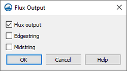
The flux output calculates of flow and constituent mass across strings. To assign flux to a feature arc, right-click on the arc and select the Assign Flux command to open the Flux Output dialog. The Flux Output dialog contains the following options:
- Flux output – Turn on to include fluz output calculations in the model run.
- Edgestring – Select if the flux output is to be calculated along the edge of the mesh domain.
- Midstring – Select if the flux output is to be calculated from internal strings inside the mesh domain.
Sediment Diversion
- Sediment diversion
- Edgestring/midstring
- Edgestring
- Midstring
- Top elevation of the zone of withdrawal
- Bottom elevation of the zone of withdrawal
- Bottom elevation of the main channel
- Edgestring/midstring
Arc Transport Constituents
Select Transport Constituents
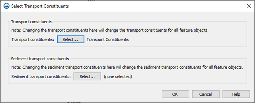
When working with transport constituents, the transport constituent component in the simulation needs be attached to transport constituents attributes assigned to feature objects. In the Project Explorer, right-clicking on the AdH boundary condition coverage and selecting the Assign Transport command will being up the Select Transport Constituents dialog. This dialog allows assigning the transport feature object attributes to the transport components.
- Transport constituents – Clicking the Select button in this section will being up the Select Transport Constituents dialog. In the Select Transport Constituents dialog, the transport component can be assigned to the coverage.
- Sediment transport constituents – Clicking the Select button in this section will being up the Select Sediment Transport Constituents dialog. In the Select Sediment Transport Constituents dialog, the transport component can be assigned to the coverage.
Point Attributes
The Point Attributes dialog is reached by right-clicking on a point in the AdH boundary conditions and selecting the Assign Point Attributes command. In the dialog, the Point type option have several boundary condition attributes for the selected point. The following Point type options are as follows:
- "Off" – No attributes will be assigned to the point.
- "Velocity and depth (DB OVH)"
- X velocity
- Y velocity
- Depth
- Stationary lid elevation (DB LDE)
- Elevation
- Depth of water under stationary lid (DB LDH)
- Depth
- Floating stationary object (DB LID)
- Draft of lid
- Wind Definition (OP WND)
- Wind
AdH Materials
AdH Sediment Materials
AdH Simulation
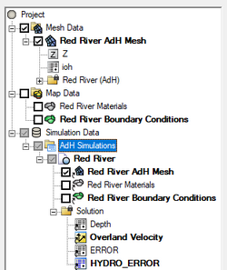
Simulations are available for AdH starting in SMS 13.3. A simulation should contain a 2D mesh and an AdH boundary conditions coverage, and optional AdH coverages. Right-clicking on the simulation will display options and dialogs.
To create a new simulation:
- Right-click on empty space in the Project Explorer and select New Simulation | AdH. A new tree item
 will appear.
 - Drag and drop simulation components under the newly created simulation tree item
 . Components available include:
- 2D mesh
- Boundary Conditions coverage
- Materials coverage
Multiple AdH simulations can be included in a single project.
Simulation Components
An AdH simulation uses the following components in the model run:
- 2D mesh – Any generic 2D mesh will work. Generally this mesh should be created from the Mesh Generation coverage.
- Boundary Conditions coverage – Contains arcs defining the boundary condition attributes for the model run.
- Materials coverage – Allows creating recording stations at specified nodal locations.
- Sediment Material coverage –
Each component can be added to the simulation by selecting the component and dragging it under the simulation item ![]() in the Project Explorer. Linked 2D mesh
in the Project Explorer. Linked 2D mesh ![]() and coverages
and coverages ![]() will be displayed under the simulation.
will be displayed under the simulation.
Linking Components
After a simulation has been created, components may be added to the simulation. Components are usually added by clicking on the component item in the Project Explorer and dragging the item under the AdH simulation. A link ![]() is then created between the component and the simulation.
is then created between the component and the simulation.
Components can also be added to a simulation by right-clicking on the component in the project explorer and selecting the simulation name in the Apply To submenu. The Apply To submenu becomes available once a simulation has been created.
Components can be removed by right-clicking on the component link under the simulation and select Remove.
If a component is updated, it must be reapplied to the simulation.
Running the AdH Simulation
After all components have been added to the simulation and the model parameters have been established, the simulation can be run. This is done by right-clicking on the simulation and choosing the Run Simulation command or the Save and Run Simulation command.
The simulation run involves three steps.
- Exporting the AdH files – SMS writes out an AdH folder in the same directory where the SMS project is saved. The AdH folder has several files which have mesh geometry information, and boundary conditions as well as model control information defined in the model.
- Running AdH – After using a launch command, the Simulation Run Queue dialog will appear. If there are any errors in the model run, the model wrapper will exit early. The model run can also be exited early by clicking the Abort button. When the model run is completed, select Exit to close the model wrapper.
The Load solution button appears with the model run has finished. Clicking this button will load the solution into SMS.
AdH Model Control
Time
Iteration
Operation
Output
Constants
Hot Start
Advanced
SMS – Surface-water Modeling System | ||
|---|---|---|
| Modules: | 1D Grid • Cartesian Grid • Curvilinear Grid • GIS • Map • Mesh • Particle • Quadtree • Raster • Scatter • UGrid |  |
| General Models: | 3D Structure • FVCOM • Generic • PTM | |
| Coastal Models: | ADCIRC • BOUSS-2D • CGWAVE • CMS-Flow • CMS-Wave • GenCade • STWAVE • WAM | |
| Riverine/Estuarine Models: | AdH • HEC-RAS • HYDRO AS-2D • RMA2 • RMA4 • SRH-2D • TUFLOW • TUFLOW FV | |
| Aquaveo • SMS Tutorials • SMS Workflows | ||
