GMS:Borehole Cross Sections
A borehole cross section is a set of polylines and polygons that define the stratigraphy between two boreholes. A borehole cross section can be created manually or automatically.
Contents
Creation
Cross sections can be created either automatically or manually.
Automatic Creation
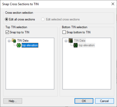
Cross sections can be created automatically using the Boreholes | Auto-Create Blank Cross Sections menu command. This uses a triangulation process to determine the most likely connections between boreholes. The top and/or bottom arcs of the new cross sections can be warped to match the elevation of TIN surfaces using the Snap Cross Sections to TIN dialog which appears when the Boreholes | Auto-Create Blank Cross Sections command is executed. Snapping the tops and bottoms of cross sections to TIN surfaces can also be done at any time via the Boreholes | Advanced | Snap Cross Sections to TIN menu command. Keep in mind, however, that warping the top and bottom of a cross section may interfere with the internal polygons that are defined in the cross section, so snapping to a TIN is best done before filling in the cross sections.
Manual Creation
Cross sections can be created manually by using the Create Cross Section tool and clicking on boreholes.
Editing
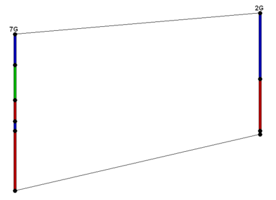
When a borehole cross section is first created, it is made up of a set of default lines. The figure below shows a default cross section. Notice that "arcs" (polylines) have been created defining the top and bottom of the cross section and an arc (polyline) has been created for each segment in the boreholes.
Automatic Editing
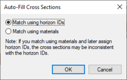
The Boreholes | Auto-Fill Blank Cross Sections menu command can be used to automatically fill in all existing blank cross sections. The command can use either the horizon IDs (preferred) or materials information on the boreholes.
Manual Editing
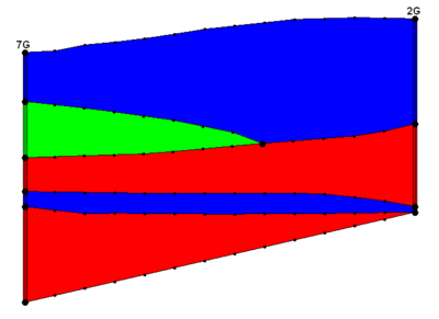
To edit a cross section manually, use the Select Cross Section tool and select a cross section. The Cross Section Editor dialog can be then opened by selecting the Cross Section Editor command from the Borehole menu while either a single or a series of cross sections selected. It is also possible to launch the Cross Section Editor dialog by double-clicking on a single cross section. The next figure shows a finished cross section.
Restrictions
GMS imposes the following restrictions on cross sections that should be kept in mind when editing:
- All polygons must be connected to boreholes
- All arcs must connect to borehole contacts
Borehole Cross Section Editor
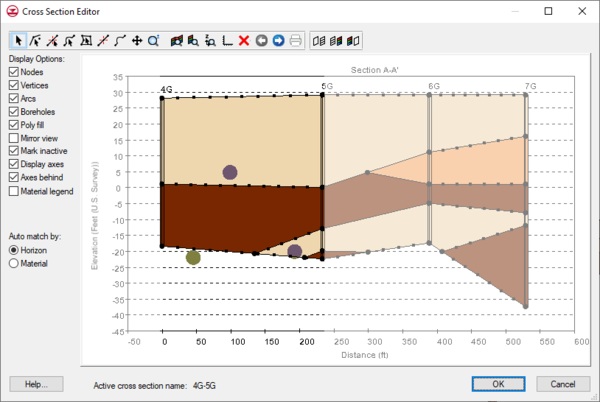
The Cross Section Editor can be used to manually construct and view cross sections between boreholes. The Cross Section Editor in GMS 6.5 has been updated to allow for the display and editing of multiple borehole cross sections. The Cross Section Editor has a set of tools and toggles used to create, edit, and view the cross sections. The tools used to create the nodes, polylines, and polygons are similar to the tools available in the Map module used to create feature objects (points, arcs, and polygons). The following tables describe the tools and display options available in the Cross Section Editor.
Tools
Display Options
| Display Toggle | Description |
|---|---|
| Nodes | Controls the display of the nodes in the graphics window |
| Vertices | Controls the display of the vertices in the graphics window |
| Arcs | Controls the display of the arcs in the graphics window |
| Boreholes | Controls the display of the arcs in the graphics window |
| Poly fill | Controls the display of the polygons in the graphics window |
| Mirror view | Reverses the order in which the cross sections are displayed |
| Mark inactive | Dims the inactive cross sections |
| Display axes | Controls the display of the plot axes in the graphics window |
| Axes behind | When checked, the axes are drawn behind the cross section. When unchecked, the axes are drawn on top of the cross section. |
| Material legend | Controls the display of the material legend |
| GMS – Groundwater Modeling System | ||
|---|---|---|
| Modules: | 2D Grid • 2D Mesh • 2D Scatter Point • 3D Grid • 3D Mesh • 3D Scatter Point • Boreholes • GIS • Map • Solid • TINs • UGrids | |
| Models: | FEFLOW • FEMWATER • HydroGeoSphere • MODAEM • MODFLOW • MODPATH • mod-PATH3DU • MT3DMS • MT3D-USGS • PEST • PHT3D • RT3D • SEAM3D • SEAWAT • SEEP2D • T-PROGS • ZONEBUDGET | |
| Aquaveo | ||
