GMS:Convert Cross Section To Coverage
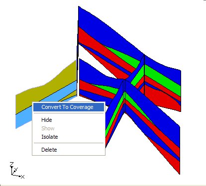
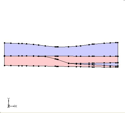
Cross sections can be converted to coverages by right clicking on the coverage and selecting the Convert To Coverage command. The outer boundary of each material zone is converted into arcs and polygons are automatically built.
When this command is executed the user is prompted to select where the new coverage(s) should be created in the project explorer. If the user wishes to have the materials from the cross section assigned to the appropriate polygons in the coverage then the user should select an appropriate conceptual model. The conceptual model must support the assignment of materials to polygons (MODFLOW, SEEP2D/UTEXAS, FEMWATER).
Coordinate Transformation
The coordinates of points from the cross section are transformed into the XY plane. The x coordinates are calculated relative to zero where zero is defined as one end of the cross section. Currently the end of the cross section that is designated as zero is the end with the minimum Y coordinate. If the cross section is horizontal then the end of the cross section with the minimum X is used.
The x coordinates are calculated by finding the distance of the point from the end of the cross section that was set as zero. The Y coordinates are calculated by subtracting the minimum z value of the cross section from the z value of the point (y = z - z_min).
Limitations
- The cross section must be vertical.
- The cross section must be a single panel (when viewing the cross section in plan view it appears as a single line segment).
GMS – Groundwater Modeling System | ||
|---|---|---|
| Modules: | 2D Grid • 2D Mesh • 2D Scatter Point • 3D Grid • 3D Mesh • 3D Scatter Point • Boreholes • GIS • Map • Solid • TINs • UGrids | |
| Models: | FEFLOW • FEMWATER • HydroGeoSphere • MODAEM • MODFLOW • MODPATH • mod-PATH3DU • MT3DMS • MT3D-USGS • PEST • PHT3D • RT3D • SEAM3D • SEAWAT • SEEP2D • T-PROGS • ZONEBUDGET | |
| Aquaveo | ||

